How Laws of Nature Control Your Stamping
April 1, 2008Comments
Every day human laws are broken—often through ignorance and sometimes by intent. Even if caught, having to pay the consequences can be sporadic, random and rare. In contrast, the laws of nature, often personified as Mother Nature, are really the laws of physics that detail the forces that hold our universe together. Actions not consistent with the laws of nature will result in immediate consequences, usually nature’s corrective actions that are independent of your design intensions. The only you can violate the laws of nature is with the immediate payment of a penalty. Numerous examples of how laws of nature interfere with metalforming are available.
One key law states: the lowest-energy mode of forming will prevail unless an extra quantity of external energy (the penalty) enters the system. The simplest example is a three-point air bend (Fig. 1A). The goal is to bend sheetmetal to the shape of the punch. Assume in Fig. 1A that this requires seven elements of the sheet to change from a flat blank to the curvature of the punch. Each element must create both elastic and plastic strains to achieve this shape change.
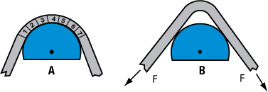 |
| Fig. 1—Schematic A shows complete bend contact with the punch, with seven segments contributing to the bend. Schematic B shows a hinge deformation in only one or two segments, causing kinking with a smaller bend radius. |
For higher-strength or thinner sheetmetal, a lower-energy form of deformation over the punch is a localized hinge effect called kinking (Fig. 1B). Kinking can be detected easily by measuring the inner radius of the bend and comparing it to the outer radius of the punch. Two corrective methods prevent kinking, but each requires extra energy (paying the penalty). One is increasing the back tension (F) at the ends of the blank to force conformation of the sheetmetal to the punch contour. Another is applying a stiff rubber pad to the area of the blank that kinks. A strong spring or nitrogen cylinder attached to the pad provides the extra energy to force the blank to remain in contact with the punch.
The above bending example was a tension-compression deformation mode. Preventing buckles in sheetmetal when formed only in the compressive mode is more challenging.
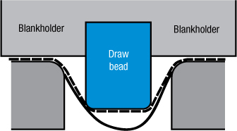
The most common example is the outer portion of circular blank moving radially toward the die radius to form a cylindrical cup. Each element of the blank under the blankholder compresses in the circumferential direction as the circumference decreases in length. However, instead of all the elements in the blank uniformly decreasing in circumferential length and increasing in thickness, the sheetmetal tries to form a series of buckles. That is the deformation mode of least energy. Here the extra energy (penalty) inserted into the forming mode is the increased blank-holder load.