


Deep Drawing Box Shells
October 1, 2017Comments
Consider the four corners of any deep-drawn box: If the sides of the box were removed, the remaining corner radii could be assembled into a cup with a square flange (Fig. 1). Thus, the corners of a deep-drawn box form in a manner that is similar to cup drawing. The corners will be compressive on the material moving toward the die radius and tensile on the material that has been drawn over the radius. Material flow in the sides and ends of the box includes simple bending and straightening, which places the material between the corners—the sidewalls and flange areas—in tension. Since drawing strains in the corners are relieved by allowing some material to flow sideways into the straight section, larger drawing-reduction ratios are achievable for box corners than for cups of equal diameter.
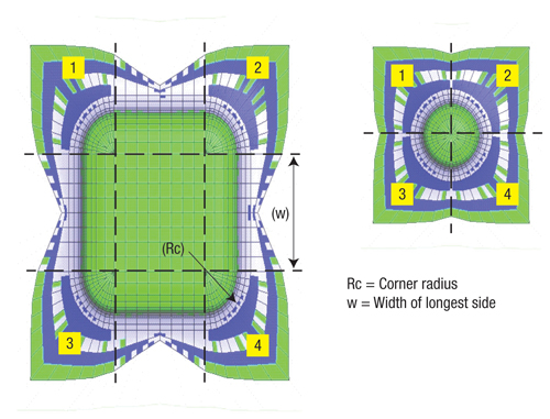
Fig. 1—The four corners of a box shell assemble into a cup with a square flange.
Because producing corners and sidewalls involve different forming modes and complex material flow, several factors must be considered when deep drawing box shells. These may include the size of the corner radius, the ratio between the corner radii and length of the longest sidewall, material thickness, material type, size of the radius at the bottom of the shell, width of flange, shape of blank, the type of die, and the type of press. Of these, the size of the corner radius through the center of material, and the ratio between the corner radii and the length of the longest sidewall, represent the two primary design factors.
The maximum drawing depth for a square box with four sides of near equal length is limited by the size of the corner radii. These depths traditionally have been estimated using tables similar to Fig. 2 and are readily found in many die-design and metalforming handbooks.
|
Corner Radius through center of material 0.000 - 0.187 in. radius 0.187 - 0.375 in. radius 0.375 - 0.500 in. radius 0.500 - 0.750 in. radius more than 0.750 in. radius |
Depth of Draw times corner radius 8 7 6 5 4 |
To determine the maximum depth of draw for a given rectangular box shell using the formability curve, the corner radius (Rc) is divided by the width of the longest side (w) of the box. The Rc/w ratio is found on the horizontal axis and a vertical line is plotted until it intersects with the first curve (Fig. 3). A perpendicular line then is extended from the intersection point on the curve to the vertical hmax/w axis, which provides the maximum height-to-width ratio for a single drawing step. Using simple algebra, we can solve for hmax, which represents the maximum height to which the rectangular box may be safely drawn in one forming operation.
For example, assume we have a rectangular shell with 2-mm corner radii and the longest side (flat portion) of the shell is 30 mm. Thus, Rc = 2 and w = 30:
Rc/w = 2/30 = 0.067,
When 0.067 is plotted to intersect the first curve, we find: hmax/w = 0.35,
Substituting for w gives:
hmax/30 = 0.35
Thus: hmax= (30)(0.35) = 10.5
That means that a box shell with a corner radius of 2 mm and the longest flat side measuring 30 mm may be safely drawn in a single operation to a height of 10.5 mm.
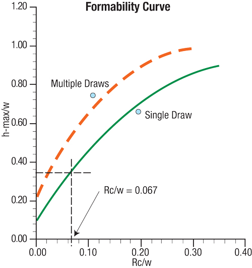
Fig. 3—Formability curve for rectangular box shells
An additional benefit of the formability curve: It allows quick analysis of inverse relationships, where one parameter (Rc) is increased as the other parameter (w) is decreased.
When the depth of the box already is known, h/w and Rc/w can be plotted on the forming curve. If the plotted point falls within the large area under the solid curve, the part may be formed safely in one operation. If the point falls within the area between the dashed and solid curve, the part might be formed in one operation providing that all of the forming conditions are ideal and/or superior materials and lubricants are used. If the point rests above the dashed curve, more than one forming operation is required.
In addition, be sure to mind the following:
- Provide additional punch-to-die clearance in the corners to accommodate material thickening. CNC machining the punch or die cavity with simple offsets for maximum material thickness will not account for material thickening in the draw corners.
- The blankholder must be relieved (spotted in) to accommodate flange thickening in the draw corners.
- Draw beads, not excessive blankholder force, may be required between the corners to retard metal flow and prevent wrinkles or waves from forming in the walls.
- In some cases, the drawing ratio may need to be reduced to alleviate splitting in the corner-radii corners. Accomplish this by cropping material at 45-deg. angles at the corners. Referring back to Fig. 1, the assembled corner radii of the box form a drawn cup, but the cup is being drawn from a square blank. Cropping the corners at 45-deg. angles reduces the drawing ratio by more closely approximating a round blank.
- Further reduce forming severity by developing an optimum blank shape, increasing die-profile radius and improving lubrication.
- Boxes with nonvertical (tapered) walls are more susceptible to wall wrinkles. Increase blankholder force and decrease allowable box height. A box with tapered walls exceeding 20 deg. may require a decrease in draw depth by 25 percent or more. MF
View Glossary of Metalforming Terms
Technologies: Quality Control, Tooling
Comments
Must be logged in to post a comment. Sign in or Create an Account
There are no comments posted. Quality Control
Amrol Jr. New Starrett President and CEO, Other Executives N...
Wednesday, March 5, 2025
Ascential Technologies Appoints Divisional CEO to Specialty ...
Wednesday, April 24, 2024
 Materials
Brinell, Rockwell and Vickers Hardness Testing: Use and Misu...
Daniel Schaeffler Friday, April 1, 2022
Quality ControlTroubleshooting Sheet Metal Forming Problems, Part 2: The St...
Daniel Schaeffler Friday, February 26, 2021