


Hole Extrusions—Part 3
December 1, 2011Comments
When the amount of stretching required to form a hole extrusion exceeds the residual stretchability of the punched hole edge, fracturing occurs at the end of the extrusion. Last month we presented several options to restore the edge stretchability of punched holes, including improving the quality of the original cutting operation and making an additional cut of higher quality. The best option: a shaved cut. After a hole has been shaved, we also can coin a small (0.020 in.) radius on the bottom side to compress any burrs that may serve as stress risers.
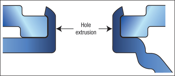
Fig. 1
 |
| Fig. 2 |
With the punched hole properly prepared, it’s ready to be extruded. Whenever possible, extrude the hole in the direction opposite of punching. This subjects the sheared edge—less damaged by cutting than the fracture zone—to the most deformation.
Most extrusions are used to produce tapped or threaded hole features. However, the inside diameter of some extrusions also may serve as a bearing surface, while the outside diameter of others serve as location hubs.
Extrusions also may be rolled or orbital-formed to create attachment points to other stampings (Fig. 1). Here, residual edge ductility is of prime concern since the extrusion flange is subjected to additional deformation after forming the extrusion.
Regardless of their final use, all hole extrusions are produced through a combination of sheetmetal bending, stretching and compressing. This action generates a tremendous amount of pressure, heat and friction. Long production runs require use of premium tool steel, extreme-pressure lubricants and highly polished working surfaces with wear-resistant coatings. To optimize punch life, metalformers must provide lubrication at the point of operation, especially during punch extraction.
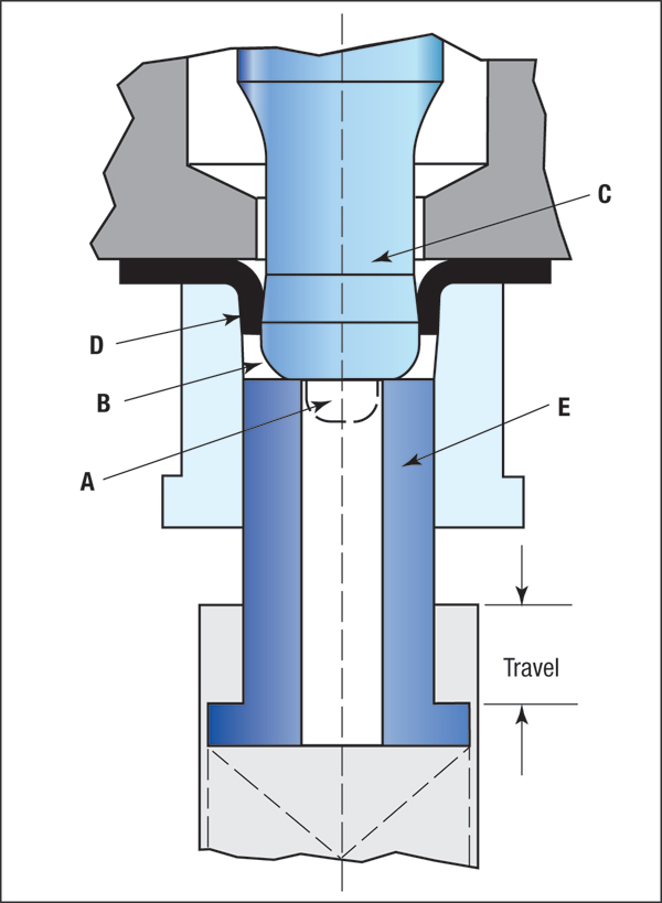
The best tooling materials and coatings, however, cannot compensate for inadequate tool design or manufacturing quality. Fig. 2 illustrates a proven tooling arrangement for forming hole extrusions. The tool must provide a pilot point (A) for location in the pre-punched hole. The extrusion punch nose radius (B) must blend perfectly with the straight section of the punch. Both areas must be highly polished, preferably along the working direction of the punch, as this portion of the extrusion punch is subjected to extreme heat and pressure. Under these conditions, a very small scratch, unperceivable to the naked eye, will quickly lead to galling in just a few press strokes.
 |
| Fig. 3 |
The die button (D) requires a tapered wall on the inside diameter to facilitate easy removal from the die matrix. Provide at least 1 deg. of taper—more if the tolerance band for the extrusion O.D. allows.
Finally, be sure to provide a knockout pin inside the die matrix (E) to help lift the extrusion from the bushing. This is especially important to prevent misfeeds in progressive dies.
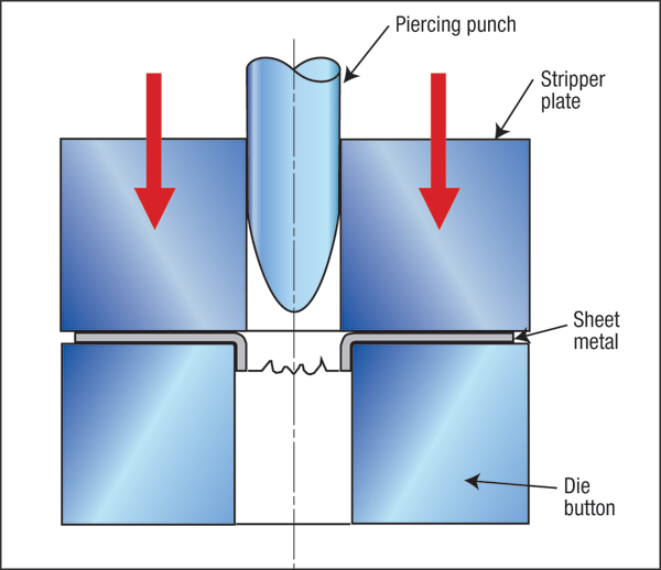
Another type of extrusion is the pierce extrusion. The difference between this type of extrusion and a hole extrusion: a pierce extrusion does not produce a slug. These extrusions als develop fractures (Fig. 3) and dimensional stability is very unpredictable. These extrusions are usually used as locating features or screw-attachment points for assembled structures with little or no loading conditions. MFView Glossary of Metalforming Terms
Technologies: Finishing, Quality Control, Tooling
Comments
Must be logged in to post a comment. Sign in or Create an Account
There are no comments posted. Quality Control
Amrol Jr. New Starrett President and CEO, Other Executives N...
Wednesday, March 5, 2025
Ascential Technologies Appoints Divisional CEO to Specialty ...
Wednesday, April 24, 2024
 Materials
Brinell, Rockwell and Vickers Hardness Testing: Use and Misu...
Daniel Schaeffler Friday, April 1, 2022
Quality ControlTroubleshooting Sheet Metal Forming Problems, Part 2: The St...
Daniel Schaeffler Friday, February 26, 2021