


Handle Elastic Stresses to Manage Springback and Improve Dimensional Stability
September 1, 2012Comments
A stamping that holds water has been the historical press-shop goal since humans first transformed sheetmetal into useful objects. While still important, major emphasis has shifted to producing stampings with accurate and robust dimensions, as required by the part print. A primary cause of dimensional instability is springback, driven by elastic stresses at the atomic level.
Elastic stresses are proportional to yield strength. Each coil of sheetmetal has unique initial yield strength (A in Fig. 1) and a corresponding quantity of elastic stress and springback at the start of permanent (plastic) deformation. To change the flat sheet or blank into the final stamping profile, the sheetmetal must undergo different types and amounts of strain (deformation). Any added deformation (B) workhardens the material, increasing its strength and elastic stresses. Springback relief of these elastic stresses causes shape and dimensional changes in the stamped part. If the deformation profile of the stamping remains constant during a production run, the elastic stresses would return to a constant lowest-energy state and we’d experience dimensionally consistent stampings. 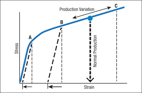
Fig. 1—Initial yield strength (A) and springback (arrow below base) at the start of permanent deformation. All additional deformation (A to C) increases strength and springback.
Unfortunately, some areas of a stamping require large amounts of localized deformation. Examples include tight bend radii, character lines, draw beads and embossments. This localized deformation usually creates a strain gradient (Fig. 2) that can become very steep with critical changes in peak strain, elastic stresses, springback and dimensional variation. The amount of deformation can vary significantly (B to C in Fig. 1).
In some cases the die creates gradients not shown on part prints, such as adjacent flat and curved surfaces that do not join in a smooth, tangential fit (Fig. 3A). The sharp change of direction is a gradient source, as are die-section joints not in the same plane (Fig. 3B). We can use circle grids or other surface-strain measurement systems to detect and measure these gradients on stampings. Then we must determine if an obvious feature of the stamping is creating the gradient, or the cause lies with a die discontinuity located below the gradient location.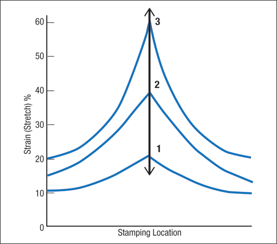
Fig. 2—Curve 2 provides a stamping with proper springback and dimensions. Process changes can generate gradient swings between Curves 1 and 3, causing major changes in springback and stamping dimensions.
In one recent case at a metalforming company, stampings made in the morning exhibited a 40-percent peak strain and a background strain of only 10 percent (Curve 2 in Fig. 2). These were normal production values and the stampings passed dimensional checks. After lunch, one or more process variables—perhaps excessive heat in the summer—changed the background strain to 15 percent, causing the gradient strain to jump proportionately to 60 percent (Curve 3). Since elastic stresses are proportional to the flow stresses, the stamping changed shape. During the late evening, second-shift workers noted that background strains had dropped to 5 percent, with a gradient strain of 20 percent (Curve 1). While the background strains varied by only 10 percent during the run, they experienced a significant 40-percent change. The stamping dimensions fell above and below normal buyoff values (Fig. 1B to C).
Making matters worse, the constancy-of-volume rule requires that the increased stretch in the gradient be balanced by local thinning. Increased thinning at the gradient site acts like a hinge, magnifying or restricting the springback problems as the gradient grows or shrinks. In this case, an ultrasonic thickness gauge proves useful to detect gradients in stampings without the application of grids or other surface-strain measurements.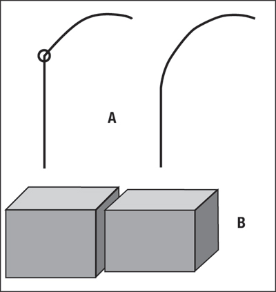
Fig. 3—Die source of gradients: A) Two surfaces not joining tangentially, shown at circle; B) Die sections with gaps or misaligned in height or in front.
The sheetmetal minimizes or maximizes gradients, but does not generate them. The workhardening exponent (n-value) of the stress-strain curve shown in Fig. 1 is what controls gradient growth. A higher stress at the gradient site initiates greater strain than in the surrounding material. For an n-value of zero, no workhardening allows the maximum gradient to form. A low n-value allows workhardening and makes the gradient site stronger as it forms. This restricts the growth of gradient formation. Conversely, a high n-value can completely prevent a gradient from forming, forcing strain to redistribute elsewhere in the stamping.
For traditional high-strength low-alloy steels, n-value is proportional to yield strength. Increasing yield strength by 45 ksi could lower the n-value by 0.10. A change in n-value of only 0.02 can have a major effect on strain distribution. The increase in yield strength for automotive weight reduction helped drive the development of advanced high strength steels (AHSS). The primary goal of AHSS alloys such as dual-phase and TRIP (transformation-induced plasticity) steels is to increase n-values without changing yield strength. MFView Glossary of Metalforming Terms
Technologies: Quality Control
Comments
Must be logged in to post a comment. Sign in or Create an Account
There are no comments posted. Quality Control
Amrol Jr. New Starrett President and CEO, Other Executives N...
Wednesday, March 5, 2025
Ascential Technologies Appoints Divisional CEO to Specialty ...
Wednesday, April 24, 2024
 Materials
Brinell, Rockwell and Vickers Hardness Testing: Use and Misu...
Daniel Schaeffler Friday, April 1, 2022
Quality ControlTroubleshooting Sheet Metal Forming Problems, Part 2: The St...
Daniel Schaeffler Friday, February 26, 2021