 |
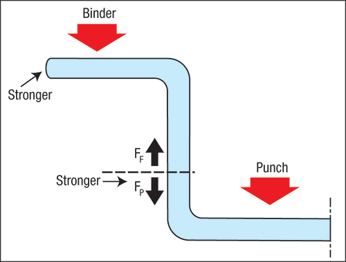
| Fig. 2—Higher yield-strength materials create a higher forming force (FF) due to increased force to achieve flange deformation, bend/unbend over the die radius plus greater friction. However, the pulling force (FP) also is strengthened by the higher yield strength to balance out the higher forming forces. |
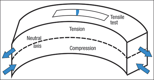
A small punch radius for a given sheet thickness creates a high peak stretch. Moving a from the peak reduces the amount of stretch, so that the allowable stretch then depends on the microstructure of the steel near the convex surface. The amount and thickness of inclusions, porosity, grain size, work hardening and other features can strengthen or degrade the amount of allowable stretch prior to tearing or cracking of the sheet surface. Studies show that the amount of peak stretch in a bend at fracture is proportional to the total elongation determined by a tensile test. If blanks fail during bending, a common press-shop troubleshooting procedure is to turn the blanks over. If only one surface exhibits poor stretchability due to inclusions, subjecting that weak surface to compression on the concave side may save the blanks.
In contrast, the cup-drawing forming mode provides some fascinating results. By designing a cup that forms well with low-strength steel, the forming mode proves insensitive to yield strength and will form well with high-strength steel. The binder area (Fig. 2) requires more force (FF) to pull the higher strength material toward the die opening as the surface area compresses. And, the material workhardens during the bend/unbend sequence as the workpiece moves over the die radius into the cup wall. However, the material transmitting the pulling force of the punch (FP) also has a higher strength. Therefore, the cup can be successfully drawn to its same depth.
These results have been proven mathematically and experimentally. Two-piece steel beverage cans are produced by a sequence of draw, redraw, three ironing stages and a bottom-dome forming operation. The DR-9 steel grade is cold-rolled to a thin sheet, annealed and then given another 35-percent cold reduction. The steel forms in the full-hard condition without failure. The secret in making the beverage cans: use of compressive-forming processing stages.
Instead of the plastic (permanent) deformation previously discussed, stiffness and springback relate to elastic stresses. Pressing down on a flat surface, such as a car roof or refrigerator door, with a force less than the yield strength causes an elastic bowing of the sheetmetal. Resistance to the force is the material’s stiffness. Releasing the force allows the elastic bowing to spring back to its initial configuration.
The amount of deformation created by a specific force (stress) depends on the elastic modulus, or Young’s Modulus, of the material. Steel has a high modulus (30 million) that creates a relatively stiff panel. Many nonferrous materials, such as aluminum alloys, have an elastic modulus of only 10 million. For the same force placed on a panel, an aluminum alloy will exhibit three times the amount of deflection or reduction in stiffness as steel. Likewise, when the force is released, springback from aluminum is three times that of steel.
Increasing the yield strength of the material does not change its elastic modulus. It merely allows more panel deflection and springback before the onset of plastic (permanent) deformation. Weight-reduction programs increase yield strength to offset the reduction in sheet thickness. This may balance load-carrying capacity, but the thinning of the panel reduces its geometric stiffness. This limits the amount of panel weight reduction, unless additional design changes are incorporated.
Whether designing a new panel with higher-strength steel or upgrading an existing panel, designers must start by analyzing the stamping to identify the forming modes, and understand the interactions among adjoining modes. Then we can acquire strain directions and magnitudes for analysis, and make decisions about forming severity and necessary design changes. MF
Keeler, Peter Ulintz and Ed Tarney will present the popular Deep Draw seminar on March 13, 2013 in Livonia (Detroit), MI. Learn more and register to attend at www.pma.org/meetings.Industry-Related Terms: Alloys,
Aluminum Alloy,
Annealed,
Bending,
Die,
Draw,
Drawing,
Flange,
Form,
Forming,
Inclusions,
Layer,
Springback,
Surface,
Thickness,
Work HardeningView Glossary of Metalforming Terms Technologies: Quality Control