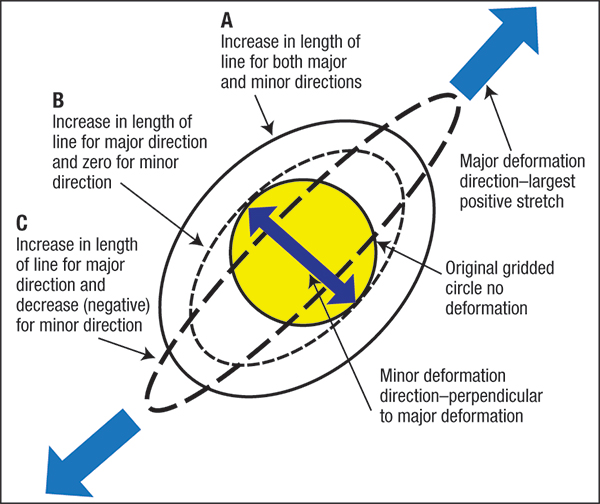
Likewise, case B elongates in the major direction but is prevented from deforming in the minor direction. This mode—plane-strain deformation—results from design features that prevent deformation in the minor direction, such as lock beads, sharp bends parallel to the major direction or very wide strips of sheetmetal. Case C experiences tensile stretching in the major direction, yet allows the minor direction to reduce the length of line because the material has little or no restraint in the minor direction. This occurs, for example, when elongating a tensile-test strip.
Tensile stretching has two restrictions. First, the deformation found in the circle on the sheet’s upper surface equals the deformation in an identical circle on the sheet’s bottom surface, and everywhere through the thickness between the two circles. This occurs often for thin sheetmetal and for die features with generous radii. However, severe bending of the material, or other processes that change the stress states and resulting deformation from one surface to the other, is not allowed.
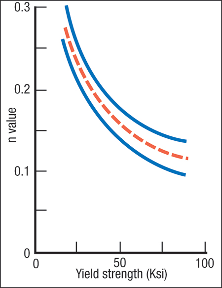 |
| Fig. 2—Graph showing approximate n-values for low-carbon mild and high-strength low-alloy steels. |
Second, all metalforming must follow the constancy-of-volume rule, which states that during deformation material is neither created nor destroyed. The final thickness of the stamping at a given location is controlled by the combination of major plus minor deformations. Therefore, forming mode A in Fig. 1 will create the greatest amount of thinning because both the major and minor deformations are positive or elongating. Forming mode C will experience the least amount of thinning because the negative minor deformation helps to feed material into the positive major deformation.
Stampings rarely have large areas of constant surface strains, and therefore the thickness of the final stamping varies from point to point. Highly localized features such as character lines, corner radii, embossments and other areas of high stretch usually experience severe thinning that leads to local necking and ultimately tearing.
A material’s work-hardening exponent (n-value) controls the localization of thinning in deformation gradients and the maximum amount of thinning before the onset of local necking. A decrease in n-value increases the amount to thinning in deformation gradients and decreases the amount of thinning allowed before local necking (given by the forming-limit diagram). That is why n-value is such an important formability property.
The metallurgical processes that increase the yield strength of higher-strength steels also reduce n-value (Fig. 2). For true tensile stretching, the old rule of thumb rings true-—increased yield strength causes design and forming problems because of reduced forming capability.
Be careful when interpreting Case C in Fig. 1. The most common failure is an excessive tensile force in the major direction and the resulting reduction in length of line in the minor direction. However, the same elongation values can be created in Case C by a strong compressive force in the minor direction that forces the workpiece to extrude in the major direction. Very high levels of major deformation can result. One example is the sharp vertical corners of an enameled vegetable crisper pan for refrigerators. One pan had major elongation of 320 percent, with a corresponding increase in thickness caused by a large compression in the minor direction. The n-value no longer limited the maximum deformation. Tensile stretching in the major direction would have torn at much lower values of stretch.
To illustrate the differences between tensile stretching and compressive deformation with a material with an n-value of 0—no work hardening—consider a full tube of toothpaste. Squeezing (compressing) the tube easily generates a long ribbon of toothpaste. However, attempting to pull (tensile stretching) a ribbon of toothpaste from the tube instantly results in local necking and tearing. Similarly, compressive deformation, when applied correctly, can create stampings from higher-strength materials that cannot be made by tensile stretching.
Next month we’ll discuss some interesting differences found during bending and cup drawing, and what controls stiffness and springback. MF
On February 5-6, 2013, in Indianapolis, IN, Stuart Keeler will present a double seminar covering Sheetmetal 101—Understanding the Metal, and Forming Sheetmetal—Understanding the Properties. Complete information can be found at www.pma.org. Industry-Related Terms: Bending,
Case,
Circle,
Corner,
Die,
Drawing,
Form,
Forming,
Lines,
Strips,
Surface,
ThicknessView Glossary of Metalforming Terms Technologies: Quality Control