


Compressive Forming-Asset or Liability?
April 1, 2012Comments
Mention metalforming and discussion turns to lack of material stretch needed to create the necessary stamping lengths of line, how higher-strength steels become brittle and fracture too easily or springback that requires too many die recuts. Occasionally, someone expresses concern about compressive forming creating buckles. Few realize that compressive forming may be hiding in numerous forming operations.
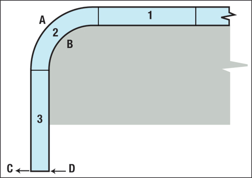
Fig. 1—Simple bending causes zone two to generate tensile deformation in the convex side (A) and compressive deformation in the concave side (B) of the bend. Tensile (C) and compressive (D) elastic stresses act to create springback, forcing the bend angle to open.
Examine a simple bend (Fig. 1). The deformation is limited to zone two, while zones one and three remain in their as-received state. The convex or outer portion of the bend (A) is formed by tensile stretching the material to meet print geometry. Stretching causes the material to workharden—yield strength increases and its capacity to stretch decreases. Excessive stretching the outermost material causes a ductile fracture. Fracture strain often relates to the total elongation measured in a tensile test. In contrast, the concave or inner portion (B) forms by compressive deformation that does not initiate fracture. Between regions A and B lies the neutral axis, which remains undeformed.
Removing the forming load at the end of deformation causes elastic stresses to return to their lowest energy state, causing springback. Tensile stresses in the upper half of the bend contract and cause the sheetmetal to pull a (C) from the formed angle (Fig.1). Unfortunately, the concave side of the bend contains compressive stresses that expand, adding to the springback by pushing (D) in the same direction as the tensile stress. This cooperation between opposite stresses is called a mechanical advantage.
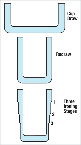 |
| Fig. 2—Full-hard steel can be drawn, redrawn and three-stage ironed to form a beverage container, because these forming modes are compressive. |
The problem of compressive deformation becomes more complex when moving sheetmetal approaches a die or punch radius, bends around the radius and then straightens again in a part wall or other feature (Fig. 1 —zones one, two and three). First, the amount of deformation doubles when the sheet first bends and then is unbent. A more formable material is required. Second, which surface will fail first, the convex or concave surface? Most will predict the outer convex surface A will fail first, however in practice, surface B most likely will fail first. When the material changes from zone one to zone two, the outer surface stretches similarly to the simple bend described above. Then the material straightens as it moves to zone three. This requires a compressive deformation accompanied by even more cold work. However, the upper zone becomes thicker from the compressive deformation, and failure is avoided.
A completely opposite sequence of deformation occurs in the concave half (B). As the material bends from zone one to zone two, the concave portion enters compression. Like tensile deformation, compressive deformation also workhardens the material, increases its yield strength and reduces its capacity to stretch in tension. After bending, the concave side of the bend (B) now is subjected to a tensile stretching that exceeds the greatly reduced capacity of the compressed material to stretch. Side B fails.
Stretching is a dangerous mode of forming, while compressing is not. Therefore, als follow tensile deformation by compressive; avoid following compressive deformation by tensile.
For some applications, such as stamping beverage cans, compressive forming represents an excellent forming mode. When two-piece beverage cans first were made, the first forming operation comprised a cup draw in a die that made six cups/stroke. Each cup then transferred to one of six other presses called body makers. In one stroke, each press would redraw a cup into a smaller-diameter cup with a longer body length (Fig. 2) and form the redrawn cup through a three-stage ironing die that reduced the cup wall thickness, causing a backward extrusion of the wall material that increased cup depth. The starting material (DR-9 tin-coated steel) is considered full-hard steel and the process does not have any intermediate annealing stages. Subjecting full-hard steel to compressive processing that actually strengthens the sheetmetal while thinning the final product provides an excellent example of combining forming science and correct product design.
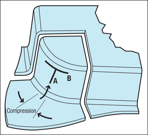 |
| Fig. 3—The compressive strains formed in the binder as the sheetmetal moves toward the die radius cold-works the material and reduces its allowable stretchability. A secondary operation creating a circumferential tensile stress can cause fracture A, while a vertical tensile stress can cause fracture B. |
Yes, areas of some stampings formed by compression do fail. The workhardening created by any mode of forming—tensile or compressive–can reduce the stretchability of the workpiece material to almost zero. Troubleshooting these failures require the engineer to ask: “What generated the final, fatal tensile stress?”
The corner of a deep-drawn box is a favorite failure area. During forming, the corner undergoes compressive deformation (Fig. 3). Assume a plan-view corner radius of 1 in. When removed from the pullover plug, the shape of the box adjusts itself so that residual stresses move to their lowest energy state. The corner radius could increase because of springback. If the second die has the same or smaller corner radius than the first die, a horizontal tensile stress could generate a vertical failure parallel to the corner (Fig. 3A). If buckles occur in the binder area and lock the sheetmetal at the die radius, a tensile stress is generated vertically along the corner, causing a failure perpendicular to the corner (Fig. 3B). The same failure can occur when insufficient clearance is allowed between punch and die ring. MFView Glossary of Metalforming Terms
Technologies: Quality Control
Comments
Must be logged in to post a comment. Sign in or Create an Account
There are no comments posted. Quality Control
Amrol Jr. New Starrett President and CEO, Other Executives N...
Wednesday, March 5, 2025
Ascential Technologies Appoints Divisional CEO to Specialty ...
Wednesday, April 24, 2024
 Materials
Brinell, Rockwell and Vickers Hardness Testing: Use and Misu...
Daniel Schaeffler Friday, April 1, 2022
Quality ControlTroubleshooting Sheet Metal Forming Problems, Part 2: The St...
Daniel Schaeffler Friday, February 26, 2021