


Breakage Case Study—Data Prevails Over Instinct
December 1, 2012Comments
Too often, stamping-plant workers use instinct rather than data to solve breakage problems, particularly during die tryout. To illustrate how data can lead us to the root cause of failure and provide feedback during corrective modifications, consider a case study involving stamping a backing plate for automotive drum brakes in a sequence of ten dies. Three dies (first, second and seventh) form two identical embossments on the backing plate, part of the hydraulic cylinder system that actuates the brake shoes. During production, embossments began to tear in the seventh die.
Before zeroing on this troubling die, let’s take a close look at each embossing station. At the first die, a hemispherical-shaped punch forms the start of the embossment near the top edge of the backing plate. The entire length of line stretches from sheetmetal within the die opening—no binder material pulls into the die opening. The lower curve in Fig. 1 illustrates the distribution of stretch from the die radius across the pole of the dome to the opposite die radius. The reduced stretch near the pole results from friction that restricts material flow, while adjacent material stretches without punch contact. The two stretch peaks indicate a ring of localized stretch developing in the dome.
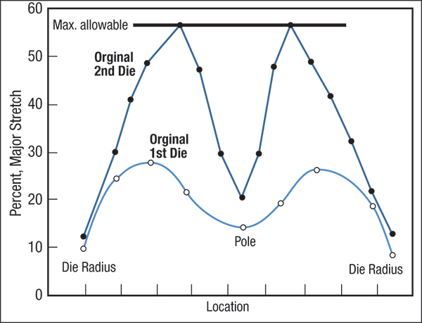
Fig. 1—Graphs showing the distribution of stretch created in the first and second dies.
In the second die, a redraw operation converts the hemisphere into a reduced-diameter higher dome. The upper curve in Fig. 1 shows that dome height increases primarily from the continued increase in stretch in the highly localized deformation gradient around the dome. To maintain constancy of volume, this ring of deformation is thinning. Note that the stretch of each peak has just reached the maximum allowable stretch as defined by the forming-limit curve.
Now to the seventh die, which, following major contour changes to the backing plate in dies three through six, performs a final restrike. This extra deformation brings the dome dimensions to part print, but also causes the embossments to exceed maximum allowable stretch. Tearing results, and die rework becomes necessary.
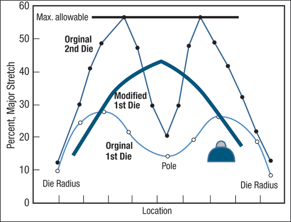 |
| Fig. 2—The heavy line shows the distribution of stretch created by the first die after modification with a small-diameter ball of weldmetal on the pole. |
Wait a minute, though. Fig. 1 indicates that embossment stretch level is critical as the backing plate leaves the second die. Should the second die be modified? The data in Fig. 1 suggest leaving the second die unchanged. First, reducing the level of stretch would be difficult. Second, general forming rules indicate the best correction is to generate the most stretch (up to 90 percent) in the first forming die, and restrict the second forming die to the minimal stretch needed to match part print. This would be analogous to parking a car in a home’s garage—you drive rapidly up the drive, then slow down when entering the garage to allow time to judge the stopping distance to the end of the garage. The stretching sequence in Fig. 1 is equivalent to spiking the stretching rate as the stamping approaches the needed dimensions. More area created under the first die curve generates a greater length of line that can be used in the second die to form the final geometry, with a minimum increase in the stretch gradient.
Increasing stroke length and dome height in the first die will only cause the existing stretch gradient and peak stretch to grow from current values to strain gradients more like those of the second die—not a good solution. However, the relationship between the stretch distribution from the first and second dies provides an excellent solution. Note that the amount of stretch at the pole is low for the first die, and can be increased. That approach is favorable because the second die creates very little additional stretch at that same pole location.
The distribution of stretch created by a hemispherical punch depends on punch diameter: the smaller the diameter, the more concentrated the distribution. A very small radius can create a distribution with the shape of a mountain peak.
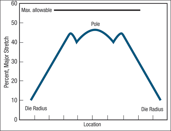 |
| Fig. 3—Approximate stretch distribution obtained with the modified first die and the original second die. Failure in the seventh die was eliminated. |
To solve this forming problem, we can modify the first die by welding a second smaller hemisphere to the pole of the original first die (Fig. 2). Thus, the blank initially contacts the small hemisphere and generates a high amount of stretch around the pole area. As punch travel continues, the blank contacts the surface of the original hemisphere, which spreads out the stretch distribution (black heavy line in Fig. 2). This greatly increases the area under the curve and the total amount of length of line available for the second die.
Forming the brake backing plate with the modified first die and the original second die produces a more desirable strain distribution (Fig. 3). The maximum stretch in the stamping has a sufficient safety margin to compensate for normal process variations. This makes dimensional variations more robust for dimensional stability, an important requirement for this stamping. Also, we’ve eliminated the severe stretch gradients previously generated in the second die, and the stretch curve essentially has a flat top.
Rather than undergoing a major tool rebuild, we’ve solved the breakage problem by simply adding a small amount of weldmetal to the first die. Better yet, the data from the stretch-distribution curves helps the welder know exactly how much weldmetal is needed. MFView Glossary of Metalforming Terms
Technologies: Quality Control
Comments
Must be logged in to post a comment. Sign in or Create an Account
There are no comments posted. Quality Control
Amrol Jr. New Starrett President and CEO, Other Executives N...
Wednesday, March 5, 2025
Ascential Technologies Appoints Divisional CEO to Specialty ...
Wednesday, April 24, 2024
 Materials
Brinell, Rockwell and Vickers Hardness Testing: Use and Misu...
Daniel Schaeffler Friday, April 1, 2022
Quality ControlTroubleshooting Sheet Metal Forming Problems, Part 2: The St...
Daniel Schaeffler Friday, February 26, 2021