


A Checklist for Installing Safety Light Curtains
December 1, 2009Comments
Information provided by Mike Carlson, safety products marketing manager, Banner Engineering; http://www.bannerengineering.com/.
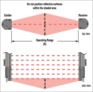
Installed near a press, robotic cell or other piece of manufacturing equipment, a safety light curtain detects the presence of an opaque object such as a finger or hand and sends a stop signal to the safety-related controls of the machine to stop the hazardous motion before the person can reach the hazard. Light curtains must be installed between the machine hazard and all personnel, in accordance with requirements specified in accepted standards. Metalformers installing light curtains should:
1) Review procedures and manuals, including the light-curtain installation manual and the company’s procedures for performing work on the particular machine being safeguarded.
2) Identify the hazard or hazardous area to be guarded, ensuring that additional hazards have not been overlooked.
3) Determine the separation (safety) distance, where the sensing field is no closer to the hazard than the determined distance, as described in the installation manual. Generally, the sensing field should not be less than 4 in. from the hazard and typically is more than 12 in. a.
4) Ensure the hazards cannot be accessed by reaching over, under, around or through the sensing field; additional guarding may be required.
5) If the safety light curtain or interface to the machine control is configured for a manual reset, ensure the switch or the means to perform the reset is outside the guarded area, located to allow the switch operator unobstructed view of the entire guarded area, out of reach from within the guarded area and protected against unauthorized or inadvertent operation. If any areas within the guarded area are not visible from the reset, provide additional safeguarding.
When mounting the light curtains, installers should ensure that the mounting surface can support the weight of the sensors, brackets, cables and hardware. Mount the emitter and receiver so that the sensing field is no closer to the hazard than is determined by the safety distance, and ensure they are aligned in a common plane and level/plumb and square to each other (vertical, horizontal or inclined at the same angle and not tilted front-to-back or side-to-side). Avoid locating the sensing field near a reflective surface, which could reflect sensing beams around an object or person and prevent its detection.
Attach the required cables to the sensors and route the sensor cables to the junction box, electrical panel or other enclosure housing the safety components of the control system. Ensure that power is not available to the actuators or any other device that can cause a hazard prior to making any electrical connections to the machine. Then set configuration options—depending on the model, some options may have been previously set; refer to the installation manual. Make initial electrical connections as detailed in the installation manual; do not connect the safety outputs until performing the initial alignment and checkout procedures.
Apply power to the safety light curtain and make final optical-alignment adjustments as described in the installation manual. To ensure the sensors are pointed squarely at each other, use a straight edge to determine the direction the sensor is facing. The sensor face must be perpendicular to the optical axis. Once the indicator(s) verify a clear or aligned condition (usually a green light), snug, but do not tighten down the mounting hardware. To optimize alignment and maximize excess gain, slightly loosen the sensor mounting screws and rotate one sensor left and right, noting the positions in each arc where the indicator(s) verify a blocked condition (usually a red light); repeat with the other sensor. Center each sensor between those two positions and tighten the mounting screws while maintaining the positioning.
When alignment proves difficult, use laser-alignment tools to assist or confirm alignment by providing a visible red dot along the sensor’s optical axis. When using mirrors to align an installation, all sensors and mirrors must be level/plumb, and the height of the midpoints of the mirrors above the floor (assuming a level floor) should be at the midpoint of the sensing field. Only one individual should move any one device at any one time.
 |
Test the detection capability by performing a trip-test procedure with the proper test piece or rod. This procedure might include the following steps:
• Select the proper test piece determined by the resolution of the sensing field. The test piece typically is supplied with the light-curtain system; if not, use an opaque cylindrical object that has a cross-section no larger than the resolution of the sensing field, such as a straight piece of PVC or steel pipe.
• Indications vary, but typically a green indicator will be on to indicate a clear sensing field.
• Pass the test piece through the sensing field in three paths: near the emitter, near the receiver, and mid between the emitter and receiver.
• During each pass, and with the test piece interrupting the defined area, the indicator must turn and remain red for as long as the test piece remains in the sensing field.
Having performed the trip-test procedure, make the required electrical connections to the guarded machine, referring to the machine documentation and the light-curtain installation manual. Perform the commissioning checkout in combination with the guarded machine; a qualified person much verify the operation of the light curtain before placing the safeguarded machine into production.
Banner Engineering: 763/544-3164; http://www.bannerengineering.com/
See also: Banner Engineering Corp.
Technologies: Safety
Comments
Must be logged in to post a comment. Sign in or Create an Account
There are no comments posted. Safety
Toolroom Safety
Peter Ulintz Monday, September 25, 2023
 Stamping Presses
Mexico Stamping Technology Webinar Series 2023: Day 2
Thursday, March 30, 2023
 Webinar
  Safety
Pilz Digital Maintenance-Safeguarding System an Efficient Al...
Thursday, March 16, 2023