Material Cards for Metal Forming Simulation
June 14, 2021Comments
Material cards are computer files containing specific material properties needed for simulation purposes. For sheet metal forming simulations, a material card should contain, in its most basic form:
- Flow stress (hardening curve)
- Yield function
- Failure criteria.
Flow Stress/Hardening Curve
 The hardening curve, by definition, is the true-stress/true-plastic-strain curve in the rolling direction, as determined by a tensile test. However, most simulation-software packages require a hardening curve up to a true plastic strain value of 1, corresponding to a 172-percent engineering strain. Of course, most metal alloys cannot withstand that level of strain in a tensile test.
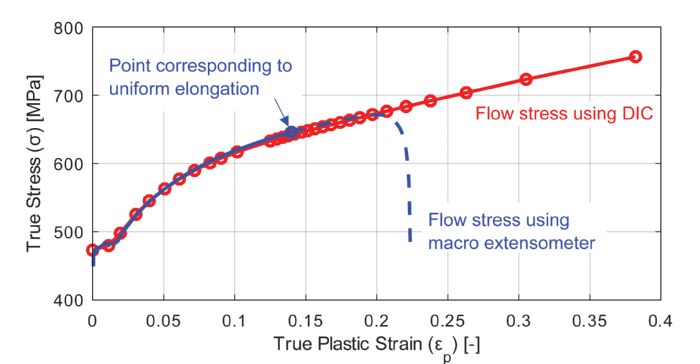
Consider here the hardening curve for high-strength low-alloy steel with a 420-MPa minimum yield strength (steel designed as 420X, HC420LA or CR420LA, for example). One sample of this steel had about 15.4-percent uniform elongation (as defined by ASTM), corresponding to 0.14 true plastic strain. Even when digital image correlation (DIC) is employed, maximum true plastic strain is just short of 0.4 (Fig. 1).
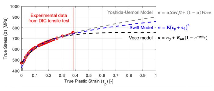 To develop a hardening curve that reaches a 1.00-true-plastic-strain value, several material models have been developed. Most sheet metal grades can be modeled using three models (Fig. 2):
- Power laws (the Hollomon, Swift, Fields and Backofen models), where flow stress is equal to true plastic strain to the power of n, with or without some modifications. Flow stress increases to infinity as true plastic strain increases.
- Saturation models (Voce, Hockett-Sherby), where flow stress saturates after some true plastic strain and becomes constant; it typically is used for aluminum alloys.
- Combination models (Hollomon-Voce, Swift-Voce or Yoshida-Uemori), a combination of the power law and saturation model. Typically, in the form of x * Power + (1-x) * Saturation.
Most software packages allow designers to input the parameters of these models. If not, the software most likely will allow the import of tabulated data.
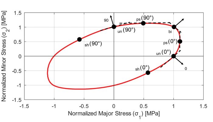 This may be one of the most complicated set of parameters to comprehend, and to experimentally determine. While we can calculate true stress from true plastic strain in simple tension or compression (i.e., uniaxial loading), when deformation is multiaxial the relation between stress state and strain increment becomes complicated.
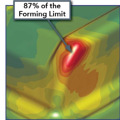
 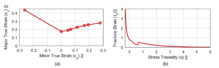 Predicting when a part will split is extremely challenging. Most simulation software relies on the forming limit curve (FLC, Fig. 4a), which works pretty well with mild steels and some high-strength steels. However, its applicability to advanced high strength steels is questionable. Plus, determining the FLC requires a significant amount of experimental work—at least 15 experiments with DIC.