Friction in Sheet Metal Forming
August 28, 2024Comments
When simulating a sheet metal forming process, one of the most overlooked parameters is the coefficient of friction. Some companies have produced a magic number, say 0.15; others use different coefficients of friction for different coatings—0.15 for uncoated, 0.12 for galvanized, 0.11 for galvannealed, for example. In reality, friction depends on many factors, including but not limited to:
 Contact pressure
- Sliding velocity
- Interface temperature
- Surface roughness of the tool
- Surface texture of the sheet
- Lubricant type and amount.
Tests to Measure Coefficient of Friction
To determine the friction coefficient, technicians select among several different types of tests (Fig. 1), including:
 Pin-on-disc
 - Twist compression
- Bending under tension
- Strip-draw
- Draw-bead
- Cup-draw
- Hemispherical stretching.
Some of these tests, such as pin-on-disc and twist compression, use deformed sheet as the test progresses. However, during sheet metal forming, tools contact undeformed sheet in every case. In this article I’ll focus on the strip-draw test.
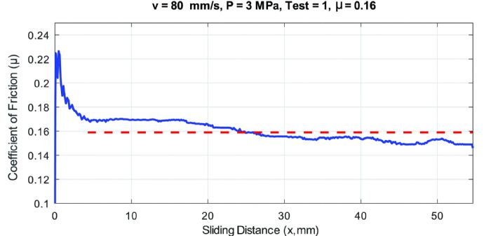
During a strip-draw test, clamping force (Fc) is adjusted using a screw, or with a hydraulic system. Then the test apparatus pulls the sheet at constant speed as researchers record the pulling force (Fp). In simple test setups, the clamping force is measured only once before the test. In better test setups, clamping force also should be recorded during the test. Then we can calculate the instant coefficient of friction (μ):
μ = Fp/(2Fc ) (equation 1)
Fig. 2 illustrates the typical output of a strip-draw test. An average is calculated in the flat region, shown with the red dashed line.
Generating a Friction Model
Some metal forming simulation-software packages allow users to enter an equation or tabular data to include the effects of sliding velocity, contact pressure and rolling direction. The effect of rolling direction can be significant when stamping some aluminum alloys. A study performed at Mondragon University reveals that in flat areas, contact pressure can range from 3 to 15 MPa, while in curved areas contact pressure may average around 20 MPa but can reach100 MPa in peak contact areas.


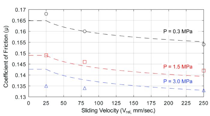 Fig. 3 illustrates test results for a friction model between tool steel and a 3rd Gen 980-MPa steel. The dashed lines represent calculations using the above equation and nine experiments, using a reference velocity of 25 mm/sec. and a maximum of 250 mm/sec. The reference pressure was 0.3 MPa, with a maximum pressure of 3.0 MPa. All results fall within realistic values.