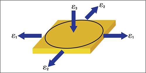
Fig. 1 illustrates another analysis problem: Are major stretch (Ԑ1) and perpendicular minor stretch (Ԑ2) both positive as shown in the figure? Or, is minor stretch (Ԑ2) actually a negative (compressive) stretch? Instead of the major stretch direction being in danger of tearing because of an elongating tensile force, it is being created by a compressive minor stretch that tends not to tear.
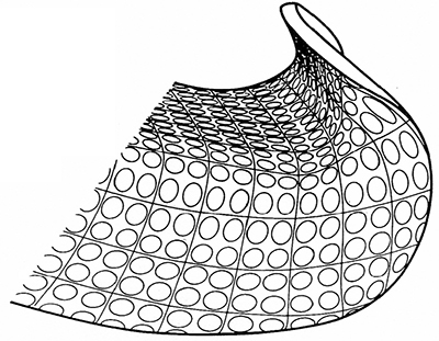 |
| Fig. 2—Circle-gridded stampings provide stretch values and major/minor strain directions at each location, plus gradient curves and other information. |
What actually happens in a real stamping can easily be measured using circle grids etched in the blank (Fig. 2). This practice can display actual numerical stretch changes and severity rankings from point to point. Stampers can use an ultrasonic thickness gauge to measure changes in thickness that result from local stresses caused by specific die configurations, lubrication, workhardening and other factors.
As sheetmetal deforms, strength increases while workhardening capacity (n-value) decreases. Therefore, higher-strength steels with lower n-values lack the power needed to prevent the formation of stretch gradients. This leads to severe stretch localization and early failure. Lower n-values also cause lower values on the forming-limit curve (FLC) that cause early onset of sheet tearing (see accompanying chart).
Bend
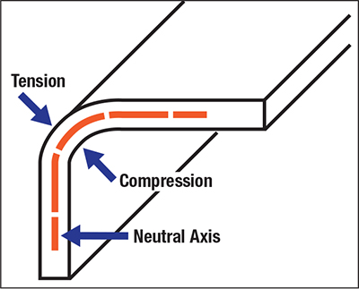 |
| Fig. 3—The three zones in a static bend or bend/ straighten deformation. Failures occur at the tension zone surface. |
A bend comprises three components: outer tensile zone (the failure site), neutral axis and inner compressive zone (Fig. 3). Let’s assume that a very thin tensile sample is embedded just inside the surface of the outer layer. During bending, the length of the outer zone must increase just like a tensile sample. Deformation continues until reaching total elongation and a tear appears. The majority of elongation prior to tearing results from workhardening. Higher-strength steels have lower n-values, which control lower total elongations (just like the tensile test); stretching and bending capacity both are a function of n-value.
The compressive (inner) half of the bend does not fail because there is no tensile stretch during pure bending. However, the material still workhardens. The reduction in n-value drastically reduces the ability of the lower zone to be straightened. Very little inner stretching will initiate fracture. The ratio of the radius to thickness controls the severity of the bend (graph). Increases in total elongation (more stretchability) lead to decreases in r/t ratio before fracture.
Cup Draw
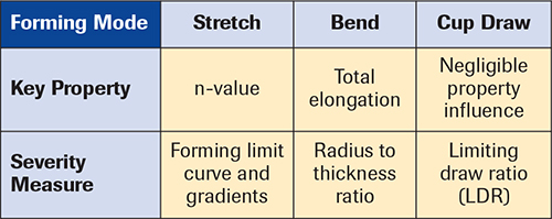 During cup drawing (deep drawing), a circular blank is drawn into a cavity by a flat-bottom punch. Material properties do not seem to play a major role when compared to the stretch and bend forming modes. To test formability, we draw a blank with a given diameter into the die cavity to form a cup. If no failure occurs, we divide blank diameter by punch diameter to generate a draw ratio.
To fully test the tool design, we increase the blank diameter until the cup tears. At this point we reach the limiting draw ratio (LDR). Numerous tests of different materials with the same tooling have shown an LDR range of 2.1 to 2.2. This narrow test range suggests that cup drawing is independent of material properties. As proof, several decades ago metalformers regularly formed two-piece beer cans from steel blanks. The sequence of forming: draw a blank into a cup, transfer the cup to a second press for a redraw operation to a smaller diameter but greater height, and then draw the cup through three stages of ironing to thin the wall and increase its height. These forming processes succeeded because all of the deformation was compressive. However, the confirming test was with Type DR-9 steel, a tin mill product. The steel was cold-rolled, annealed and then cold-rolled a second time to reduce thickness by 35 percent and reach the required thickness. The steel was “full-hard” but was formed without failures because the forming mode was compressive. However, any subsequent cup deformation that would have required a tensile stress would have caused the can to fail. MF
Industry-Related Terms: Surface,
Thickness,
Transfer,
Ultrasonic,
Form,
Forming,
Gauge,
Layer,
Annealed,
Bending,
Blank,
CAD,
Circle,
Corner,
Die,
Draw,
DrawingView Glossary of Metalforming Terms Technologies: Quality Control