


Sheetmetal Failures: Fracture or Necking?
November 1, 2009Comments
Press shops endure many metalforming failures. Examples are die cracking, bearings running dry, press jammed on BDC, robots misplacing blanks, and punches wearing out prematurely. A complete list of possible failures would fill a book. In contrast, this month’s topic covers a very narrow but sensitive failure found in most press shops—sheetmetal fracture or tearing caused by excessive stretching.
Two common forms of sheetmetal fracture are brittle and ductile. Fractures in glass, rocks and ice have the characteristics of brittle fracture. However, brittle fracture in sheetmetal forming is uncommon. A rare example would be a stamping that cracks when dropped on the floor because the chemistry, processing, microstructure and amount of cold work all interact just right to produce a brittle condition.
Instead, the more common brittle fractures in sheetmetal happen for specific metal chemistries when subjected to high impact loading at very low (-40 deg.) in-service temperatures. Unfortunately, too many statements are heard in press shops that deformation work hardens the steel so much that it becomes brittle and fails. Others will explain that high-strength grades or full hard tempers of sheet must be formed only once because the material already is so hard after the first hit that any added deformation makes it brittle and unable to withstand a second hit.
Work hardening increases the strength and hardness of the stamping while reducing the remaining stretchability. A second hit would require a very high force that most likely would initiate deformation in the least worked (lowest strength) area of the stamping and not at the desired location. However, exceeding the maximum allowable deformation would initiate a ductile fracture, not a brittle fracture.
The usual mode of stamping fracture is ductile fracture. The cross-sections through the sheet thickness in Fig. 1 illustrate the difference between brittle and ductile fracture. The brittle fracture (A) has no or very little localized plastic deformation surrounding the fracture. The fracture surface often occurs at a 45-deg. angle through the thickness of the sheet.
In contrast, the ductile fracture (B) has significant deformation and thickness reduction prior to the onset of fracture. One can visualize the ductile flow of material before the sheet actually tears. The resulting fracture surface has a cup and cone topography.
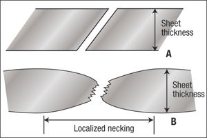 |
| Fig. 1—Fracture profiles of brittle fracture (A) without any through-thickness thinning, and ductile fracture (B) showing extensive localized thinning. |
Fortunately for press shops, the termination of useful deformation in most stampings is not the unpredictable ductile fracture. A local neck is the failure mechanism that terminates global stamping deformation. Local necking is defined as a narrow line of highly localized thinning with deformation across the neck but no deformation along the line of the thinning (Fig. 2A). The forming mode changes to a rigid sheet above and below the neck that move apart as the local neck thins and widens as total deformation force decreases. In a normal tensile-test sample (Fig. 2A), the local neck is angled about 55 deg. from the major loading axis. This is the angle along which the resultant strain is zero. As specimen width increases, the angle increases until the local neck eventually occurs perpendicular to the major strain direction. As the local neck develops, a high rate of straining occurs within the neck that eventually leads to ductile fracture (Fig. 2B).
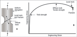 |
| Fig. 2—Schematic of a tensile-test sample (A) showing an angular local neck at the onset of fracture, and a stress-strain curve (B) with the local neck occurring just prior to the onset of specimen fracture. |
The criteria for a local neck defined above for a tensile test remains the same when forming stampings in the press shop. However, the direction of the maximum strain, as well as widely varying gradients of strain that change throughout the stamping with the stroke of the punch, make the theoretical prediction of the onset of local necking almost impossible. However, metalforming studies over the last three decades have collected sufficient data to generate experimental curves that predict the maximum allowable stretchability. Called forming-limit curves or forming-limit diagrams, these important curves and their application will be the topic of the December column.
So far the discussion has focused on excessive stretching of sheetmetal. Other types of failures occur when sheetmetal is formed compressively. For small amounts of compressive deformation of thick sheets, the compressive direction becomes smaller as sheet thickness (and sometimes sheet width) becomes larger, according to the constancy of volume rule. When the amount of compression becomes too large for a given sheet thickness, the sheetmetal simply forms buckles as the least-energy mode of deformation.
Understanding how sheetmetal interacts with the die is very important at the product design, process design and die design stages of the stamping cycle from concept to production. The primary benefit of work hardening due to deformation is an increase in strength. The payment for this mode of strength increase is a reduced stretchability as measured by the total elongation in a tensile test. The companion increase in hardness reduces surface wear. Neither increased strength nor hardness by themselves changes the failure mode from ductile to brittle. Too much emphasis is placed on fracture and total elongation as the maximum amount of allowable deformation. Virtual press shop analyses use local necking (forming limit curve) as the termination of useful deformation. So do many of the highly productive physical press shops. MF
View Glossary of Metalforming Terms
Technologies: Quality Control
Comments
Must be logged in to post a comment. Sign in or Create an Account
There are no comments posted. Quality Control
Amrol Jr. New Starrett President and CEO, Other Executives N...
Wednesday, March 5, 2025
Ascential Technologies Appoints Divisional CEO to Specialty ...
Wednesday, April 24, 2024
 Materials
Brinell, Rockwell and Vickers Hardness Testing: Use and Misu...
Daniel Schaeffler Friday, April 1, 2022
Quality ControlTroubleshooting Sheet Metal Forming Problems, Part 2: The St...
Daniel Schaeffler Friday, February 26, 2021