


Old and New Ways to Solve Forming Challenges
October 1, 2013Comments
Predicting the distribution of stretch within a stamped part has been a challenge since the early days of dies and presses. The stamping tears when the design requires excessive stretch. Buckles and floppy areas result from insufficient stretch.
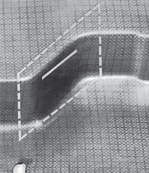 |
| Fig. 1—Automotive instrument-panel backing plate has a critical section highlighted by dashed white line box. The solid white line is the tear line. |
Modifying one area of stretch can cause an unexpected reaction throughout the entire stamping. Numerous procedures have been developed in an attempt to quantify stretch levels prior to cutting the hard tool. They range from ink-gridded rubber sheets pulled over a wooden model of the stamping to calculating percent stretch for each section line in the blueprint. While providing some measure of qualitative information, the results depend highly on the interpretation—and bias—of the evaluator.
A better to solve a forming crisis: Combine several simple yet proven quantitative measurement techniques. A case study of an automotive instrument-panel mounting plate illustrates this process. The problem section of the first draw is highlighted by the dashed white line in Fig. 1. When forming different lots of electrogalvanized steel, breakage varies from 0 to 100 percent. The solid white line represents the tear line. Studying this section, one concludes that insufficient material is flowing from the blank and/or the upper and lower die radii. This causes high local levels of strain (stretch) in the vertical direction up the wall. Some lots of steel lacking sufficient stretchability cannot withstand this high strain, and tear. The opening of the tear indicates the required length of line to achieve home depth.
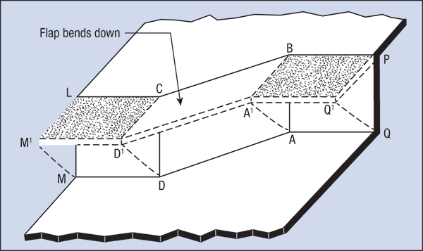 |
Consider the simple sketch (Fig. 2) of the material movement within the dashed white line zone in Fig. 1. Forming causes the two shaded zones on either side of the tear section to undergo bending and unbending, as the flat blank progresses through the die radius and then is flattened back into the final straight walls. The strain in these flat zones is almost zero. The zones on either side of the tear section can be analyzed as simple flaps of material folding down. Flap A’BPQ’ becomes wall ABPQ and flap D’CLM’ becomes DCLM.
Using actual stamping measurements of the critical section, initial line C-A’ is 1.88 in. in the blank; final line C-A in the formed stamping is 3.05 in. Using standard strain computations, line C-A stretches 62 percent. In the perpendicular direction, initial line B-D’ is compressed by -22 percent, forming line B-D and wrinkles. We confirm these quick calculations by applying circular grids to a blank and forming it (Fig. 3). The long axis of the ellipse (major strain) stretches 65 percent and the perpendicular axis (minor strain) compresses -25 percent. The measured values agree very closely with the computed values using Fig. 2.
The computed strain values and the actual circle-grid strain values from the major strain along AC and the minor strain along BD match those observed from a tensile test. The tensile test fails by a through-thickness neck and then tears at 45- to 54-deg. to the long axis. This failure axis conforms to the observed failure direction in the stamping. Also, the strains are created only by the sheetmetal being forced to conform to two adjoining flat zones of the punch. Therefore, corrective action by changing die and punch radii, blank size and lubrication would not be effective; changes to the geometry of the stamping are required. Unfortunately the die already is in production and dimensional changes are not allowed.
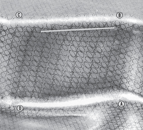 |
| Fig. 3—The greatest strain in the critical section is oriented along direction AC, as shown by the circle-grid ellipses. Failure (white line) is oriented approximately 45 deg. to direction of greatest strain. |
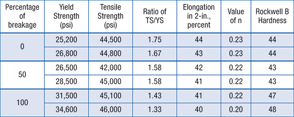
One option to eliminate tears is to change the workpiece-material properties. Fortunately, three different lots of steel had been used for production (see the accompanying table). The breakage rates were 100 percent, 50 percent, and 0 percent. Stretchability of a tensile-test sample depends on the workhardening capability of the sheetmetal. Increased stretchability is signaled by increased values of the TS/YS ratio, n-value and total elongation. The highest values of these properties belong to the steel lot having zero breakage.
Rockwell hardness is an excellent measure of resistance to scoring and other modes of surface wear, but is not a measure of stretchability. While breakage was zero for one lot of trial steel, the safety margin of those properties is unknown. The steel may be on the edge of the forming-limit curve (zero safety margin). This red flag indicates that subsequent lots of the same type of steel could suffer high breakage from variations in steel properties, lubrication, blank size and placement, die setup, die radii wear and rebuild, press adjustments and other process variables.
While this specific analysis is decades old, the fundamental data acquisition and analysis process remains valid. However, modern computer programs not only will quicken these analyses but also provide analyses so complex that the human mind cannot comprehend their interactions. Cameras can take pictures of many types of stampings with grids and produce a cloud of data points on a forming-limit curve showing which areas are safe, marginal or in danger of failure. Virtual forming programs can analyze and assess a current design, and also revisions to the stamping and die design before the first die is machined.
Given a choice, some of us still prefer to go back and occasionally visit the old s. Here we can use our technical toolbox of analytical procedures and our brains to solve a few challenging problems—often on the back of an envelope. MFView Glossary of Metalforming Terms
Technologies: Quality Control
Comments
Must be logged in to post a comment. Sign in or Create an Account
There are no comments posted. Quality Control
Amrol Jr. New Starrett President and CEO, Other Executives N...
Wednesday, March 5, 2025
Ascential Technologies Appoints Divisional CEO to Specialty ...
Wednesday, April 24, 2024
 Materials
Brinell, Rockwell and Vickers Hardness Testing: Use and Misu...
Daniel Schaeffler Friday, April 1, 2022
Quality ControlTroubleshooting Sheet Metal Forming Problems, Part 2: The St...
Daniel Schaeffler Friday, February 26, 2021