Stuart Keeler Stuart Keeler
President/owner

Is Metalforming Failure Predictable?

June 1, 2011
0
Comments


A 1957 research program on metalforming tackled two important questions:

• When, or more accurately how, does sheetmetal fail during forming?

• Can the onset of failure be predicted?

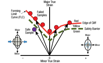
We discussed the first question in last month’s column. Failure occurs when useful forming throughout a part terminates, and all subsequent deformation localizes in a very narrow band—a through-thickness local neck. The maximum useful stretchability or tensile deformation in the stamping terminates when the local neck begins to appear. Not only does initiation of the local neck determine maximum punch travel and stamping configuration, but the visibility of the neck spoils any class-A surface. Deformation in the local neck continues until the material in the neck tears and fractures.

Stampers often overlook the importance of the local neck as they attempt to correlate its onset with properties from the tensile test—onset of the diffuse (width) neck at the load maximum, uniform elongation, ultimate tensile strength or total elongation. Instead, the onset of the local neck is a unique event and a complex material property.

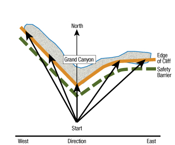
Fig. 1—Walking toward the edge of the cliff along different paths results in different travel distances.
Defining how sheetmetal fails has limited practical press-shop application unless one can predict the onset of failure, by the amount of strain and the location in the stamping. This situation is akin to walking near the edge of the Grand Canyon in the dark, wondering exactly where the edge is and knowing that going too far in the wrong direction will take you over the edge. One wrong step leads to falling off the cliff—failure, followed by a severe crash—fracture.

Knowing what occurs after falling is not useful information. What is useful? Knowing the exact distance from the starting location to the edge of the cliff, for the chosen path (Fig. 1), which proves helpful in establishing a safety zone and barrier to warn of an impending fall.

Phase II

During the second phase of the research program, scientists sought to define the edge of the deformation cliff for a variety of alloys formed into different stampings. For this they developed a circle grid, which measures the strain accumulated by the stamping (Fig. 2). Like a map of the area around the Grand Canyon, the circle grid provides the starting point (zero-by-zero strain). Instead of north/south and east/west tracking of movement, the circle grid uses major strain (largest positive strain shown as the long axis of the resulting ellipse) and minor strain (perpendicular to the major strain).

The circle grids allow tracking the deformation at every location in the stamping.

Research included samples of steel, aluminum, copper and brass, although the most extensive tests were on steel. After 10 years, the research produced the first map (Fig. 2) defining the edge of the “deformation cliff.” Final validation came after overlaying two circle grids—a laboratory-generated map and a press-shop-generated map from an automotive part using the same lot of steel. The fit was excellent. After other laborites around the world duplicated the research, the forming limit curve (FLC) and forming limit diagram (FLD) became predictive tools for the automotive, appliance, agricultural and aircraft industries, among others.

Fig. 2—Forming Limit Diagram displays Forming Limit Curve (FLC), safety margin (yellow zone), safe and failed samples, and different deformation paths within a stamping.
Additional research determined that a standard-shaped FLC (Fig. 2) could be used for most of the low-carbon sheet steel products. The FLC moves up and down the vertical axis as the lowest point of the curve (FLC0) changed value as a function of the work-hardening exponent (n-value) and sheet thickness. The equation for FLC0 changes for different metals, alloys, tempers and other variables. Fortunately, most steels need only one equation because the more formable steels are one alloy (low carbon) and one temper (soft or O-annealed).

FLC as a Stretchability Indicator

The FLC answers the original research question: How much can sheetmetal stretch? The FLC (Fig. 2) shows that a given sheet formed into a given stamping does not have a single value of maximum stretch. Instead, an infinite number of values are possible depending on the major/minor strain combination as the specific forming path intersects the FLC.

The FLC also shows the most critical path is plane strain, where the major strain has a low value and the minor strain is zero. Looking at the ellipses formed by the deformation of the circle grids, the plane-strain ellipses visually indicate the least amount of strain when they become critical. Typically, one would not consider these ellipses to be critical. In contrast, the highly deformed ellipses on the left side of the FLC usually do not approach their critical values. Therefore, without specific data from the edge of the deformation-cliff map, any answer is simply a guess.

The FLD (Fig. 2) not only shows the FLC (edge of the deformation cliff) but a zone of insufficient safety margin that allows for process variations. A numerical safety margin, initial severity readings, stamping modification tracking and other useful troubleshooting information can be plotted on the FLD. Some automotive OEMs even require an FLD severity analysis at die buyoff.

A very important application of FLC and FLD is the virtual press shop, or computerized die tryout. Here technicians can simulate forming and analyze on the computer strain localization, insufficient safety margin and risky strain paths. Process modifications can be tracked, material properties evaluated, blanks redesigned, part design optimized, etc., without machining a hard die. The shop can identify any dangerous combination of forming parameters during the design phase, rather than waiting for a job—one production disaster. MF

Stuart Keeler will present the High Strength Steel seminar on June 22 in Detroit, MI. Visit www.pma.org for information on this and other seminars.
Industry-Related Terms: Alloys, Brass, Circle, Die, Edge, Forming, Point, Surface, Tensile Strength, Thickness
View Glossary of Metalforming Terms

Technologies: Quality Control

Comments

Must be logged in to post a comment.
There are no comments posted.

Subscribe to the Newsletter

Start receiving newsletters.