Forensic Investigation—CSI in the Press Shop, Part 3
July 1, 2012Comments
The beneficial properties of higher-strength materials— their high yield and tensile strengths, and high ductility—also contribute to the degradation of tool life, and promote premature failures. Tool-failure mechanisms common in progressive dies used to stamp higher-strength materials include chipping, cracking and wear in cutting and punching operations; and galling and wear during forming operations.
For our purposes, higher-strength materials include medium- and high-carbon steels; most stainless steels; high-strength low-alloy steels; dual-phase and other advanced high-strength steels (AHSS); nickel-based superalloys such as Monel, Inconel and Hastalloy; and titanium and molybdenum sheet.
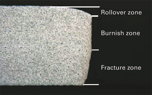
Fig. 1
Chipping and Cracking
The higher stresses required to penetrate these stronger materials require stampers to use greater cutting clearances between punch and die components, compared to the clearances used to stamp lower-strength materials such as grade 1008 steel. When cutting clearances are too tight, there will be an increased tendency for chipping and wear due to the high stripping and frictional forces acting between the work material and tooling surfaces.
Chipping often is the most common failure mechanism when cutting, punching and blanking higher-strength materials. Chipping results when process stresses are high enough to cause low-cycle fatigue of the tooling material. This indicates that the material lacks toughness. Toughness failures may result from improper material selection, faulty heattreatment or fabrication (EDM) procedures, or improper operating conditions (alignment, feed, etc.)
 |
| Fig. 2 |
Stampers also must avoid making cutting clearances too large. Otherwise, cracking may result. Cracking occurs spontaneously when process stresses exceed the tensile strength of the tooling material. Punch cracking poses a greater concern with AHSS materials due to their very high tensile strengths, which can approach the tensile strengths of the tool steels themselves.
Burr size, die rollover, burnish band and fracture zones are commonly used during progressive-die strip inspection to characterize the quality of the shear edge. Fig. 1 provides an example of these shear-edge characteristics (Konieczny, et al).
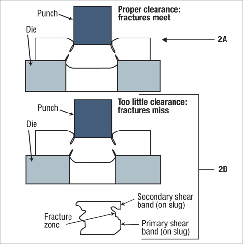
When cutting clearances are properly engineered, usually 10 to 15 percent per side, the fracture zone from the punch-cutting edge will meet the fracture zone from the die-cutting edge (Fig. 2A). But when cutting clearances are small, press and die alignment become very critical. Failure to maintain this alignment can cause the punch and die details to contact each other, damaging the cutting edges. In addition, an edge defect known as secondary shear —sometimes referred to as a double-break—can occur. Secondary shear results when the stamping fracture-zone angles from the punch edge and die edge do not meet. As a result, an additional band of metal is sheared, producing a second burnish zone as the two fracture zones try to join (Fig. 2B).
Small cutting clearances also require greater punching forces and cause greater punch wear, due to abrasion. As the pierced material grips firmly around the punch, stripping forces required to extract the punch increase. If a punched hole becomes distorted in the direction opposite the punching direction, inadequate holding pressure may be the culprit.
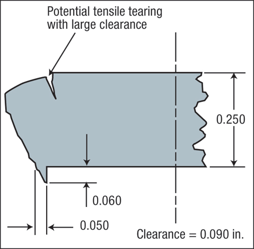
Larger cutting clearances make press and die alignment less critical, and also require less cutting and stripping forces. But, if cutting clearance becomes too great, extreme rollover occurs and undesirable burrs will be evident during die-strip inspection. In extreme cases, should the surface stretch beyond its ultimate tensile strength the sheetmetal may actually tear or break open in the rollover zone (Fig. 3). Soft, thick materials sometimes will extrude a thick, heavy burr into the large cutting-clearance gap.