


Deep Drawing—More Advanced Topics
August 1, 2008Comments
Study a number of product part drawings for deep-drawn cylindrical shells and one might get the impression that uniform wall thickness is the desired feature for all cylindrical part designs. This occurs most frequently when part designers are not aware of the natural wall thickening that occurs when deep drawing cups. But there are times when a constant wall thickness is a necessary feature in a well-thought-out product design. In either case, it is als prudent to consult with product designers to understand the intent of their designs.
For product designs that genuinely require uniform wall thickness, ironing can correct thickness variations caused by the deep-draw process. Ironing creates uniform wall thickness by controlling the clearance between the punch and the die. This may involve reducing the cup wall to a thickness equivalent to that of the original blank or reducing the cup wall below the original blank thickness in order to increase the cup body height.
Suppose that the product design requires a uniform wall thickness equivalent to the original blank. In this case, only the top (open end) of the cup wall is ironed since the wall near the bottom of the cup is already near the original blank thickness (Fig. 1).
This is acomplished by controlling the punch-to-die clearance so that no ironing occurs until the tooling contacts the thickened material. Besides producing a thinner and more uniform wall thickness, ironing also decreases the degree of earing in cups produced from a material with high planar anisotropy. Since the wall thickness in the valley between the ears exceeds that in the eared portions, the valley heights will increase when the cup wall is ironed. Although earing cannot be removed totally by this technique, a more uniform wall height will result.
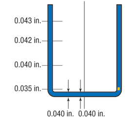
Fig. 1—Thickness Distribution
Sometimes more severe ironing is employed to reduce wall thickness below that of the original blank thickness. This usually is done to increase cup body height. Of course, there is a limiting reduction for a single ironing stage but the largest possible reduction should als be made. Unless the material is especially ductile, a 50 percent reduction in wall thickness represents a good starting point. Even though there are cases where 90 percent reduction in wall thickness has been reported for a single ironing operation, consider these unique cases where the combination and control of material properties, tooling geometry and lubrication were ideally suited for the particular process.
A common misconception is that ironing adds an additional process step
and thereby increases manufacturing costs. Contrary to this misconception is the fact that drawing, redrawing and ironing are routinely carried out in a single press stroke with tool sets similar to that shown in Fig. 2. Of course, a press with an adequate stroke length must be available to carry out the consecutive operations.
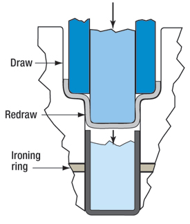
Fig. 2—Draw, Redraw and Ironing Tool
Shallow cup drawing is another type of drawing process. Similar to deep drawing, it often is performed without the use of a blankholder. Shallow cup drawing usually requires the depth of the drawn cup to be less than its diameter, but an overriding factor is the percentage of material thickness (t) relative to the blank diameter (D): % = t/D x 100
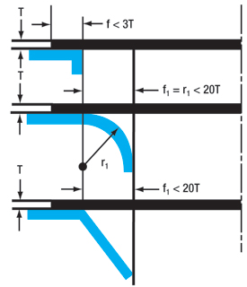 |
| Fig. 3—Radius and Bevel Design Parameters |
Other sources, including the Die Design Handbook (SME), recommend a minimum die entry radius of six to eight times stock thickness, or the use of a beveled die entry when drawing heavy-gauge material without a blankholder. It also has been found that wrinkling will not occur if the contact distance between the blank and the die face is less than three times stock thickness and the distance from the die opening to the initial blank contact point does not exceed 20 times stock thickness (Fig. 3). This rule applies to either the radius or beveled entry design. MF
View Glossary of Metalforming Terms
Technologies: Quality Control
Comments
Must be logged in to post a comment. Sign in or Create an Account
There are no comments posted. Quality Control
Amrol Jr. New Starrett President and CEO, Other Executives N...
Wednesday, March 5, 2025
Ascential Technologies Appoints Divisional CEO to Specialty ...
Wednesday, April 24, 2024
 Materials
Brinell, Rockwell and Vickers Hardness Testing: Use and Misu...
Daniel Schaeffler Friday, April 1, 2022
Quality ControlTroubleshooting Sheet Metal Forming Problems, Part 2: The St...
Daniel Schaeffler Friday, February 26, 2021