


A Case Study—Troubleshooting Score Marks
July 1, 2008Comments
Four common approaches to troubleshooting press-shop problems are 1) ignore the problem, 2) emotionally order random corrective actions, 3) blame the metal supplier and 4) undertake a logical data-based analysis of the problem. This true case study incorporates features of all four approaches. The higher-strength-steel problem part is a deep-drawn, closed-end channel with welded flanges. Separate dies in separate presses form symmetrical left- and right-hand channels. Severe sidewall scoring in the right-hand channel is a perpetual problem that no longer can be ignored.
Attempts to eliminate the scoring have focused on pursuing a long list of traditional modifications such as polishing the die, changing punch-die clearance and playing with different lubricants. One could characterize this approach as emotionally ordering random corrective actions. These attempts to correct problems almost als begin without a valid definition of the problem or a final goal.
One day, two different coils of steel produced right-hand parts with different amounts of scoring. Now the problem is obvious, the steel is the root cause. The steel supplier receives a call to attend a demonstration at the stamping plant. First, a section of coil B (for bad) produces parts. Then a section of coil G (for good) produces parts. Yes, the G-coil parts visually show somewhat less scoring than the B-coil parts. In the traditional of doing business, the representative from the steel supplier returns to his company with a mandate to supply better steel. Blaming the supplier is completed.
However, all participants have ignored the rules of good troubleshooting. First, a numerical definition of the problem is required to provide a base line or reference point. Relating back to this starting condition allows one to track progress toward the final goal or problem solution. The final goal also must be a numerical and realistic target. A goal of zero defects forever is not realistic. “It looks,” “I think,” “I know,” “I assume,” “I feel,” “it’s probably” and “I am comfortable with” are not numerical statements of either the problem or final goal.
How does one numerically define scoring of a part? In this problem, the area of the rectangle encompassing each distinct patch of scoring is measured. No scoring for 0.25 in. means that one patch has ended and another patch has started. The total area of all patches is the scoring index for that part. Measurement of multiple parts not only provides an average scoring index, but also a measure of repeatability.
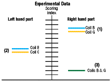
The graph shows the results from this study. The results for the right-hand part (1) show two distinct lines confirming that coil G produces
less scoring than coil B. However, the difference between the scoring index of G and B is small compared with the total scoring index. The steel coils make a difference but one or more variables play a much larger role.
Graph showing the progression of improvement during the search for the cause of sidewall scoring.
Now that the problem has a numerical definition, what is the final goal? Our steel-company representative has learned another lesson of troubleshooting. He questions the person most involved with the problem, the die maker assigned to the part. He quickly learns that the die maker never has any problems reported to him about the left-hand tool. Since everyone ignores those parts, that level of scoring must be okay. Now we have the best troubleshooting opportunity. For two symmetrical parts, one hand has the problem, while the opposite hand holds the solution. Instead of trying to find the solution from a large number of possibilities, the search now focuses on what is different between the two parts.
For a valid right-hand to left-hand comparison, performing tests with the same process conditions eliminates extraneous variables. In this case, four steel samples—coil G prime-side up and down and coil B prime-side up and down—are formed in each die. The results (2) for the left-hand part show the same difference between coils G and B as the previous results. However, the left-hand part has almost half the severity of the right-hand part. Obviously, the root cause of the problem is not the steel but the difference between the right- and left-hand dies.
To find the difference between dies, visual inspection is conducted on both sets of open dies placed side-by-side. The difference becomes immediately obvious. The intersection of a curved surface and a straight section is not tangential. This creates a sharp edge that causes galling and then scoring. Of course, the next instruction is to modify the right-hand die to duplicate the left-hand die until the scoring indexes are equal (now the numerical target).
This case study has a mixed ending. The bad news is that during the modification of the right-hand die a major mistake occurred. The good news is that when the right-hand die now makes parts, the scoring index is not equal to the left-hand part. The new right-hand scoring index (3) has dropped to nearly zero with no difference between coils B and G.

