Peter Ulintz Peter Ulintz
Technical Director

Interpreting Formability Problems

December 1, 2016
0
Comments


Understanding the capabilities and limitations of your metalforming-simulation software is necessary in order to accurately interpret and react to formability results.

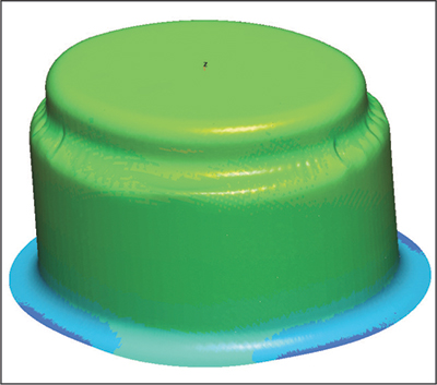
Fig. 1—Green signifies that thinning falls within the safe zone.
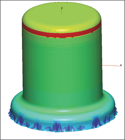
 Fig. 2—Failure near the bottom of the cup.
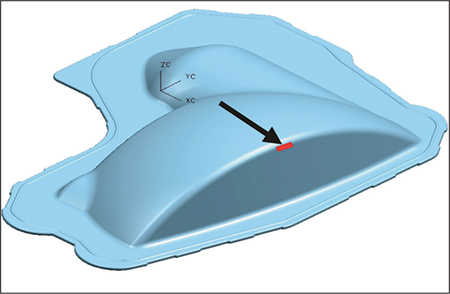
Fig. 3—Modifying the tooling configuration yields an acceptable result.

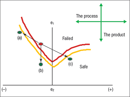
Fig. 4—Strain points must be positioned under the forming-limit curve to be considered safe.
lank-prediction software relies on simplifications and assumptions in order to minimize the amount of input data and needed calculation time. These software programs provide useful blank-prediction results quickly, but may sacrifice accuracy for ease of use and cost-effectiveness.

One-step solutions are quick and easy to use. All they require from the user are final product geometry, usually in 3D CAD format, and minimal material properties. The software takes the final product geometry and forces it into a flat blank, providing reasonably accurate blank-shape predictions. Resultant strains from flattening the part are mapped back inversely—compressive strains are converted to tensile strains of equal magnitude–onto the original CAD product geometry.

Be careful when interpreting one-step results. If the solver predicts excessive thinning or splitting failures, that does not mean that the part being analyzed could not be produced; it simply means that the part cannot be produced in a single forming step.

Flat-blank results from one-step solvers often are used as input data for incremental analysis. Here the process engineer conducts more complex analysis using precise blank shapes and specific material properties with production-intent tooling geometry. Because the blank profile, punch-face profile, die cavity, pressure pad and draw beads are all modeled for analysis, more accurate results are possible as compared to a one-step solution.

A word of caution: It is not sufficient to simply achieve green results—where all thinning strains fall within the safe zone on the forming-limit diagram. As Fig. 1 illustrates, the thinning strains in the reduced diameter are located well within the safe zone, but the material still puckers when deformed into the smaller ellipse. This phenomenon cannot be detected with one-step solvers, and some incremental codes may not have the ability to visually depict this type of defect.

Modeling tooling for incremental analysis requires great care and understanding of the forming process. Fig. 2, for example, depicts a failure near the bottom of a deep-drawn cup. An inexperienced analyst might assume that the process is not feasible (cannot be drawn to this depth) based on these results. On the other hand, an analyst that understands deformation mechanics will quickly realize that the flange of a deep-drawn cup thickens as the blank diameter is reduced. The cup in this particular example was produced from a highly formable austenitic stainless steel that can thicken as much as 40 percent per side at the open end of the shell. Here the analyst needs to modify the virtual tooling by providing material-thickness clearance plus an additional 40 percent per side at the die opening. The additional clearance should be gradually tapered back to sheet-thickness-per-side near the bottom of the cup. Reiterating the forming process with this modified tooling configuration produced acceptable results.

Sometimes real-world problems are best solved on the computer.

Suppose that the stamping in Fig. 3 had a split on the radius near the top of the panel (arrow). The intuitive solution in this case is to reduce pressure on the blankholder, or reduce friction by adding more lubricant, to allow the material to flow more freely into the die cavity. After these adjustments were made, several parts are produced only to find that there is no improvement. Additional attempts to assist material flow include increasing the draw radii and polishing it to a mirror finish, but the part still splits. The blank also is positioned on the blankholder in such a way that gravity causes the material to sag into the center of the die cavity. This seems to be a reasonable solution, as more material can reach the area that has been splitting. But it doesn’t help either.

Perhaps the blank is buckling under the blankholder before reaching the die cavity, thus restricting metal flow. Here, blankholder force should be increased, not decreased. The idea makes perfect sense and all believe a solution has been found. To everyone’s dismay, this does not work either.

Now a virtual approach—requiring the use of computer-based forming simulations to investigate what-if scenarios to obtain possible solutions—is attempted.

The initial simulation duplicates the tooling surfaces and process conditions that existed when the splitting problem first arose. The simulation results clearly show the blank buckling under the blankholder. Subsequent iterations reveal that the proper tool correction is the addition of draw beads with a specific shape profile, height and location on the blankholder. How long, if ever, would it take to arrive at this solution by guess-and-check on the shop floor?

Why did the draw bead additions work? For simplicity, let the red starburst in Fig. 4 represent a set of failed strains on the stamping. Those strains must be positioned under the forming-limit curve to be considered safe. One could try to move the critical strains to position (b) by reducing drawing strains in this area. But this would require a change in part design. Another option is to move to position (c) by changing from a drawing process to a stretching process, but that requires major tooling and process modifications. The best solution is to increase the amount of straining (by adding draw beads) and shift to position (a). MF

Industry-Related Terms: Austenitic Stainless Steel, Blank, CAD, Case, Center, Die, Draw, Drawing, Flange, Polishing, Stainless Steel, Forming
View Glossary of Metalforming Terms

Technologies: Software

Comments

Must be logged in to post a comment.
There are no comments posted.

Subscribe to the Newsletter

Start receiving newsletters.