Stuart Keeler Stuart Keeler
President/owner

Develop Die-Damage Curves to Avoid Breakage

April 1, 2014
0
Comments


When flying, do you look out at the airplane engines and wonder if they’ll continue to perform until you return safely to the ground? Or, do you sit back and relax, confident that the engines are being carefully monitored against a curve showing accumulation of damage as a function of flying hours?

Consider one such curve (Fig. 1), which shows that the amount of stamping die damage increases proportionally against use until attaining a critical mass of damage (point C). At this point we expect the die to fail; the curve dictates that the dies undergo maintenance well before reaching the critical point.

How many press shops running long-term dies use similar curves to track die damage? And, how many shops then schedule preventive die maintenance before reaching point C, to avoid major stamping rejections? Many changes in the die during production can cause damage to stamped parts, and rejection. Stamping dimensions can vary due to die wear or changes in component alignment. Friction that controls sheetmetal flow within the die depends on die-surface roughness and die temperature. Interaction of the 40 or more forming-process inputs will determine whether the damage curve has a desired shallow slope or a dangerously steep slope.

During a recent afternoon tour of a large automotive stamping plant, our group walked by the plant’s medium-sized die-build and repair shop. The repair shop was empty, with all of its machines idled. When asked why, our guide said that the shop “had completed all of the scheduled maintenance jobs in the morning, because they were minor jobs.” Note the emphasis on “scheduled maintenance,” and the implication that crash jobs on broken dies never occurred.

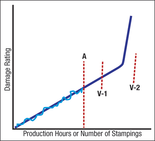
This topic was a case study during a recent PMA seminar on press-shop troubleshooting. We studied a die-damage curve (Fig. 2), which indicated (point A) the need for timely preventive action. In this study, maintenance requires five days, and the job runs 20 shifts per week, preventing the stamper from stockpiling stampings.

Discussion question: If the customer has a scheduled two-week vacation shutdown at V-1, is there a problem? Everybody in the class answered “no,” because maintenance could easily be performed during those two shutdown weeks.

Damage curve defines how much damage is done to the die based on prior stampig measurements
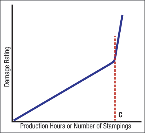
Fig. 1—The Damage Curve defines how much damage is done to the die based on prior stamping measurements. At time C, sudden excessive damage or breakdown occurs.
Real-world problems usually find a customer vacation shutdown at V-2 or greater. Now there are two possible answers:

1) Call the customer and tell them you will have to shut them down within the next three weeks; or

2) Do nothing and keep running until the die can no longer produce acceptable stampings, then call the customer with the bad news.

Most in the class suggested a third response:

“You cannot take the customer down,” they said, but failed to come up with any alternative solution.

Just as every airplane engine has a unique damage curve, so do stamping dies. First, determine the stamping failure mode. For example, if stampings exceed dimensional variation due to die wear, construct a damage curve by taking die measurements of a refurbished die at incremental times from start to failure. Plot these measurements against production hours or number of stampings. To protect against other failure modes, plot the second and third most severe failure modes as separate graphs.

Stampers have other options for determining if a stamping process is running in a stable mode, or is drifting a from job-one settings. They can use, for example, an ultrasonic-thickness (UT) gauge or circle-grid analysis to track stamping-process stability. Potential problem areas are measured at die buyoff.

The easiest and fastest procedure: Use a UT gauge to measure part thickness at critical locations. The change in thickness is proportional to the change in surface deformation (strain) at that location.

With the current die status at A, repair work can be done during customer shut down at V-1.
Fig. 2—With the current die status at A, repair work can be done during customer shut down at V-1. Customer shutdown at time V-2 means future lack of stampings.
Stampers typically pull a die at the end of a run and move it to a storage area. With a new run scheduled, the dies return to the press and production begins. An operator or inspector checks the first stampings made to verify compliance with specifications. If part dimensions fall out of spec, production ceases and repair procedures begin.

As an alternative, before pulling the die at the end of a run an inspector can use a UT gauge to check the last stamping made against the target values. If he detects a problem, the die moves to the repair bay before being stored. For more complex problems, the whole stamping can be circle gridded to study material flow in more detail.

As a variation of this procedure, the metalformer can evaluate a stamping made 2 hr. before the end of the run. If problems are detected that can be repaired with the die still in the press, the stamper can make the corrections immediately following the run. It then makes a number of stampings before it pulls the die to verify the repairs.

In some cases, stampings will pass inspection at the end of a run yet fail inspection at the beginning of the next run. Again, the stamper must compare UT readings taken on the approved stampings at the end of the previous run to those from the defective first stampings of the next run. Useful information about the die/press setup will quicken the correction process. The same procedure can be used to evaluate whether a new coil is affecting the process (last stamping/old coil compared to first stamping/new coil).

Many press shops display their most complex stampings on their walls to show potential customers. While many of these stampings look impressive, they also can hold large amounts of information. Circle-grid each stamping. After forming, neutralize the electrolyte, degrease, wash/dry and protect the stamping surface with Krylon spray. This will protect the surface and grid for decades. The stamping also remains available for UT measurements so that if the shop runs the die later or has a problem with a similar stamping, it can refer to the preserved stamping for corrective information.

Finally, when showing potential customers around the press shop, your deformation-control procedures on the stampings can be explained, making a great customer impression. MF
Industry-Related Terms: Case, Checks, Circle, Die, Forming, Gauge, Point, Run, Surface, Thickness
View Glossary of Metalforming Terms

Technologies: Quality Control

Comments

Must be logged in to post a comment.
There are no comments posted.

Subscribe to the Newsletter

Start receiving newsletters.