 “The importance of proper electrode selection and maintenance often is overlooked or taken for granted,” continues DeCorte, who has been involved with RW for more than 40 years. “Resistance welding is a mystery to many people and electrodes are one of the most misunderstood components of the process.”
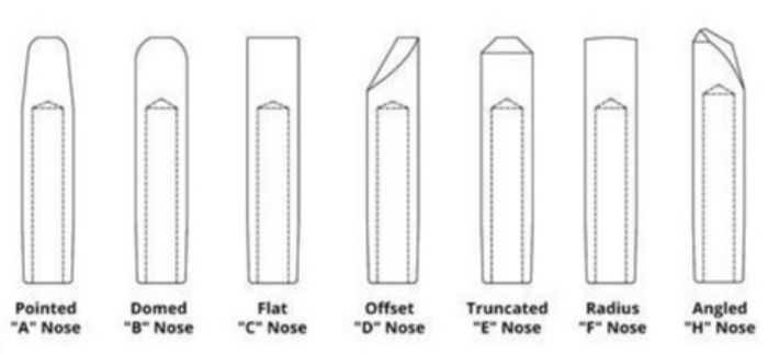 Domed electrodes find a lot of use in the automotive industry, because they can help solve alignment issues and are easily dressed in an automated process. Flat-faced tips find use for applications requiring a good “show surface,” although weld heat must be concentrated from the opposite side of the weldment with a pointed or domed-tip electrode. When making show-surface spot welds, think of the electrode’s weld face as a printing press, because each weld will leave a “picture” of the tip end.
Welding aluminum? Electrodes with a slightly radiused weld face find use here. And, according to Bill Brafford, who retired after a long career with RW electrode manufacturers CMW and Tuffaloy, “when welding galvanized material, use tips with a truncated nose, because the unavoidable expulsion will not form a ‘dam’ around the weld face.”
Well-Dressed Tips
Unlike arc welding, the RW process does not consume the copper electrodes. However, over time, the tip’s contact surface mushrooms, due to a few reasons: the heat generated from a workpiece-material’s electrical resistance; the physics of applying high weld-forging force; and the lack of supply of well-refrigerated cooling water to the electrode.
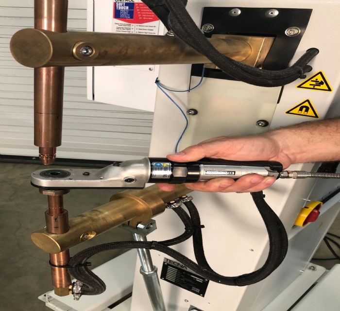
Therefore, metal formers must perform some form of tip dressing to return the electrodes to their original configuration. Dressing options include the basic, but relatively inaccurate, radiused hand file, or pneumatic dressing tools, which an operator can use while the tips remain installed in the welding machine (Fig. 2). However, for optimum results, dress tips offline in a drill press equipped with special cutter blades.
 Unique to robotic RW cells are automated tip-dressing stations, which work like a motorized pencil sharpener. For best results, program the dressing operation to occur well before the tip faces begin to mushroom and negatively affect weld quality.
Wondering about the importance of proper electrode dressing? Consider tests performed on new 1⁄4-in. weld-face pointed nose tips, and using a secondary weld current of 9800 A to produce sound welds. Allowing the tip face to mushroom just slightly, to 3/8-in. dia., which increases the surface area by 25 percent, now requires 22,100 A of weld current to form high-quality welds. Failure to increase welding current to compensate will lead to the formation of weak welds.
Caps and Shanks
To save money, consider substituting caps and shanks for standard one-piece RW tips. This combination allows you to reuse the electrode shank when replacing the small cap tips due to wear. Select from several versions of caps and shanks, including male, female, through-hole and blind-hole. Electrode shanks with blind holes allow cooling water to remain flowing while replacing the caps. However, this convenience results in faster mushrooming because cooling water does not reach as close to the weld face as it does when using through-hole shanks.
RW-equipment suppliers offer several types of cap-extracting tools. Two of note: Tuffaloy and CMW. Note: Applying a thin layer of conductive grease on the taper prior to installing tips will make them easier to remove.
Tapers
 Some RW tips have threads, but most have a tapered shank that engages with the electrode holder to provide good electrical conductivity and a watertight seal. Select from several different tapers, the most common being #5RW, an RWMA designation equivalent to a #2 Morse Taper. Other options include ISO tapers and tips from Asian suppliers; it’s important to know which style your welding machine requires.
In addition, shops can return worn internal tapers of electrode holders to their original condition using a reamer. And, never use Teflon tape or pipe compound on the taper to stop water leaks.
How Long Do Tips Last?
That’s a common question, and the standard answer is, “it all depends.” Many RW applications are unique and tip life will vary greatly based on the workpiece material, and whether the metal former has properly optimized RW-machine settings.
|
by Roger Hirsch, president of Unitrol Electronics, Northbrook, IL, a manufacturer of RW controls and recirculating water chillers. I recently received a call from the welding engineer at a Tier Two manufacturer, explaining that she had been experiencing poor electrode life from the firm’s 35 RW machines. With this many machines, replacing the copper electrodes proved quite costly, but not as costly as the lost production time required to replace the electrodes. In a 2-yr. study, the company found that it had to replace its RW electrodes 30-percent more frequently during the summer months compared to winter months. Since production load did not vary by season, I surmised that the temperature of the water being used to cool the electrodes was the culprit. Further investigation revealed that the temperature in the water tower supplying the RW machines was 15 to 20 deg. higher during the summer than the winter. The solution: Eliminate the water tower and install a refrigerated-water system in the plant’s welding department. And, as an aside, this setup also eliminated water contamination from the water tower, which periodically clogged the cooling tubes inside of the electrode holders. After installing the refrigerated-water system, electrode life improved by 25 percent when compared to the best electrode life recorded during the coldest winter months, and did not change by season. |
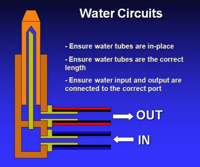
Proper water cooling is critical to long electrode life and most tips come with drilled internal water passages. Copper, brass and plastic tubes with one end cut on a 45-deg. angle will help force cooling water inside of the electrode, as close as possible to where heat is generated during the weld (Fig. 3).
Unfortunately, operators oftentimes will not understand the importance of water tubes, and will lose them or throw them away—a costly mistake. In addition, pay attention to the temperature of the cooling water supplied to the electrodes, to prolong life (see the accompanying sidebar).
When welding coated steels, such as galvanized, the tip’s weld face will tend to pick up some of the coating, and, therefore, will require dressing more often than when welding bare steel. RW of aluminum alloys can be even more challenging, since aluminum wants to alloy with the copper tips. Because of this alloying effect, the weld face may require dressing after only a few welds.
Other tip-life considerations include a solid understanding of the three main RW process variables—welding amperage, forging force and welding-current on time. To optimize tip life, seek to adjust these variables to produce the required weld strength with the shortest possible weld time. While shops can refer to charts that recommend parameter settings based on workpiece material and sheet thickness, only consider these as a starting point.
An Alternative to Offset Tips
Finally, while some applications will require the use of double-bend offset tips, to access difficult-to-reach weld locations on narrow flanges, for example, shops should avoid offsets where possible. Offsets will tend to deform due to low physical strength and poor water cooling—particularly when using expensive offset tips made from copper castings.
In place of offset tips, try using a standard, straight tip, with an offset nose mounted in an offset electrode holder. Consult available tip catalogs for illustrations of various electrode and holder combinations that will provide the required reach into challenging weld locations. MF
View Glossary of Metalforming Terms
See also: T. J. Snow Company
Technologies: Welding and Joining