Oberg offers dies designed and built to three
clearly defined standards, based on expected part volumes, quality and
product life.
Series I
Annual volumes of 20 million or more
Punch-to-die clearance less than 0.0008 in.
Die sections mounted in a channel
Spring stripper mounted on independent guide posts
Die sensors mounted in the casting, interconnected
Custom Meehanite die set
Carbide or ceramic cutting components
Premium punch construction
Carbide-tipped piloting
Series II
Annual volumes of 500,000 to 20 million
Clearance equal to or greater than 0.0008 in.
Die sections mounted on top of die shoe
Spring stripper mounted on main guide posts
Sensors surface mounted and connected with individual cables
Standard ANSI 1025 Die Set
Carbide, powdered-metal or high-carbon high-chrome cutting components
Series III
Annual volumes less than 500,000
Type A ball-bearing die set
Die sections mounted on top of die shoe
Mechanical die-protection system
Box stripper
Carbide, powdered-metal or high-carbon high-chrome cutting components
“To scale back to Series II dies,” explains Bachelier, “rather than use individual punch-die sections for easy replacement, we’ll gang sections together and incorporate more wire cutting. Sensors typically will be surface mounted rather than buried in the die, and are connected with individual cables rather than interconnected with one main cable running to the controller.” Series II dies typically are designed for annual part volumes as low as 500,000 and up to 100 million. Series III tools, for part volumes of 50,000 pieces to 200,000/yr., typically use purchased die sets and not much carbide, unless a specific area looks to be high wear. “Otherwise, we use tool steel or PM steels,” says Bachelier, “and we may specify a box stripper rather than a spring stripper.”
In most cases, medical and defense parts are run on Series I or Series II dies—it all depends on evaluating the task at hand, not only part volumes and program life but also tolerances and other quality concerns. For example, Series I dies promise punch-to-die clearance of less than 0.0008 in., with die clearance of Series II dies equal to or greater than 0.0008 in.“
Most customers ask us to build them a die based on what we think they need,” Bachelier continues. “We have the freedom to look at expected tool life, form complexity and other program parameters and, relying our stamping experience and expertise, develop the best die for the job at hand.”
Lead-Time Reduction Starts in Design
With a more diverse customer base than ever before, Oberg is able to leverage some of the design features it engineers for one customer and apply those features for its other customers’ projects. “Our CAD system stores design standards into automated design programs,” says Bachelier, “which streamlines design for the next customer. For example, we can keep dowel and screw holes in similar locations to reduce programming time, and use off-the-shelf finished components.”
This standardization has blossomed in the last couple of years—from engineering through the toolroom—and allowed Oberg to reduce programming time by at least 30 percent in most cases. And, as programming time has dropped so has cycle time (from the time die steel is cut to when a die hits the assembly bench)—as much as 50 percent in the last 5 yr., explains Bill Wallace, Oberg’s stamping-plant toolroom manager.“
We monitor each work center with our MRP system (Infor System 10) and track performance,” Wallace explains. “Last year the tooling division enjoyed a 95-percent on-time delivery rate. Using the MRP system, we can monitor work load compared to capacity at each work station, and with that data in hand we can approach management and make a strong case for capital expenditures, targeted at addressing specific capacity needs.”
A Technology Tune-up
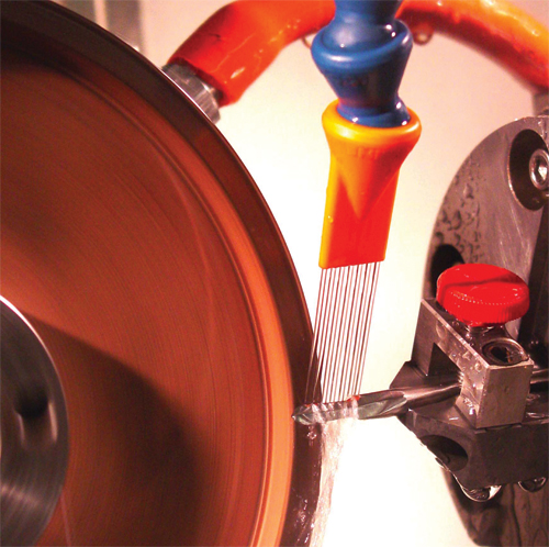
Over the last 3 yr., Oberg has invested more than $10 million in new machining equipment. It also has continued to customize special machining platforms to perform its proprietary Molecular Decomposition Process (MDP). It uses the process where surface quality of die components is absolutely critical—typically found in Series I and II dies, but occasionally specified in Series III dies as well. “
During MDP, we establish a cathode-anode relationship between the abrasive wheel and the workpiece,” Rugaber explains. “As a result, we can remove stock as much as 80 percent faster than with conventional grinding.”
Using MDP, which Oberg now has installed on more than 10 grinding machines (three of which are dedicated to toolroom activities, the rest for production machining), allows full-depth cuts to be made in one pass with surface finishes to less than 1 Ra.
In addition to new equipment, lean processes installed in recent years have allowed the firm to surpass industry standards for lead times, says Rugaber.
“We’re building the same number of tools per year that we were 5 yr. ago, with a build cycle that has gone from 18 to 20 weeks down to just 8 to10 weeks today,” he says. “And scrap and rework are down significantly.”
 |
|
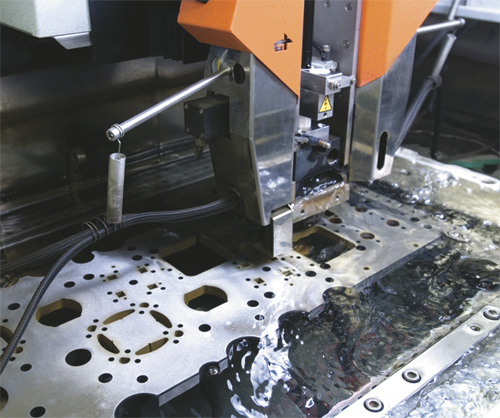
| Oberg has the same number of wire-EDM operators it had 5 yr. ago, but is sending 30 to 40 percent more product out the door. This is due, in part, to automation that enables unattended machining. |
Asked to cite where these improvements are coming from, EDM manager Jeff Ambrose quickly cites the implementation of automation—robots and palletizers, for example—throughout the EDM department.
“We have the same number of wire-EDM operators we had 5 yr. ago,” says Ambrose, “but now send 30 to 40 percent more product out the door. One operator can run eight or nine machines, if we strategically schedule the workflow to allow for unattended machining.”
Ambrose’s department is stocked with a variety of EDM machines, including 16 wire and seven sinker machines; another six wire machines are installed at the company’s Costa Rican plant. Each machine make, says Ambrose, is geared toward a specific category of operation, from basic roughing to fine machining.
“We’ve got the latest machines from Charmilles, Sodick and Mitsubishi.” he says, “and while there’s some overlap, each machine has its place. By carefully selecting the right machine for the job at hand, we optimize productivity throughout the EDM shop and keep our costs down.”
High-Speed Machining, Too
Wallace notes that the rest of the toolroom functions similarly, calling out its high-speed machining operations and noting that for Oberg, high speed truly means high speed—we’re talking up to 40,000 RPM.
“We’ve acquired more than 25 new four- and five-axis machining centers since 2007,” he says, “eight for toolroom support and the rest for production machining,” noting a trend toward stamped parts requiring value-added machining. “There’s no manual machining left here.”
“In the past, a die section would require multiple steps across multiple machines,” Bachelier adds, “perhaps to finish the tops and the sides. Now, a multiaxis machine can complete a die section in one handling. Cycle times are greatly reduced, and we eliminate setups and queue time. This has reduced machining time by 60 percent—setup time alone is reduced by 2 to 3 hr., so that a section that once took a total of 10 hr. takes just 4 hr. now. And, we can achieve a net or near-net finish and eliminate grinding in some cases.” MF
Industry-Related Terms: Abrasive,
CAD,
Case,
Center,
Die Clearance,
Die,
Form,
Grinding,
Run,
Scale,
Scrap,
Stripper,
SurfaceView Glossary of Metalforming Terms
See also: Infor
Technologies: Tooling