Considerations for Transfer-Die Design
January 12, 2022Comments
With few exceptions, transfer dies are designed much like the dies used for individual and tandem press-line operations. Important differences include maintaining all dies to a common pass line and shut height; incorporating guide pins, heel blocks and set blocks unto the upper die shoe to avoid interference with transfer rail movement; and providing clearance in lower die sections for transfer fingers to pick up and place parts.
Transfer-Die Advantages
 As compared to dies for other types of stamping operations, transfer dies can eliminate secondary operations, decrease labor costs and increase material utilization. Improving material utilization can produce significant cost savings, especially when running thick or expensive materials.
Transfer dies, not restricted by the progression of the part, can be designed to match part requirements without sacrificing material use. They enable more robust and easier-to-install form and trim punches, improving die life and serviceability.
Progressive dies, able to produce multiple parts/stroke with potentially high material utilization and operable at relatively high speeds, often provide the best solution for high-volume production. However, tooling may be complex with corresponding manufacturing risks and higher maintenance costs.
 Transfer dies can be mounted in the same press and use the same feedline as progressive dies, with parts transported from station to station mechanically rather than via carrier ribbons attached to the coil. Die construction tends to be less complex than progressive dies and provides more flexibility for rotating parts, with raw material blank- or coil-fed into the die.
Other reasons for considering a transfer die: possible elimination of offline or secondary operations; less die maintenance due to ease of serviceability and adjustment; and better process control and part quality—all acting to keep an existing transfer system busy. Note that part size dictates the use of a transfer die—part volume excludes the use of manual-load dies, with part rotation or tipping required to account for burr direction or difficult access that cannot be accomplished in a progressive die.
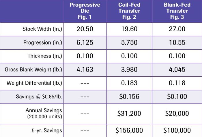
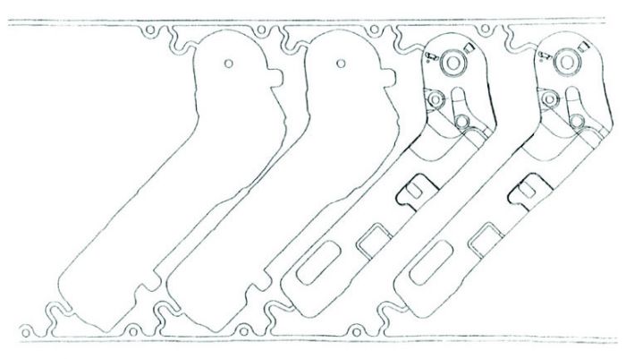
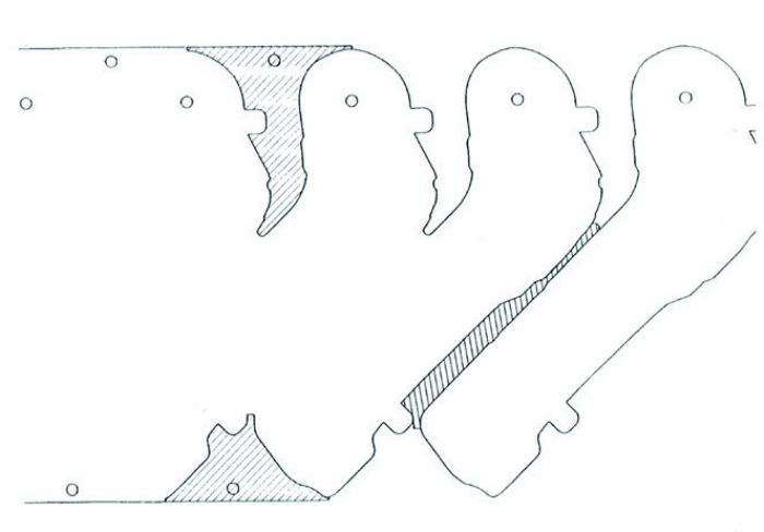 The first step: Create a strip layout for a progressive die and a flow chart for a transfer die. A flow chart shows the work to be performed in each station. Next, consider how the blank will load into the transfer die. Possible methods: coil feed, coil transfer, zig-zag feed or blank destacker. Compare the material use for several methods and calculate the cost difference (see the accompanying table and figures).
 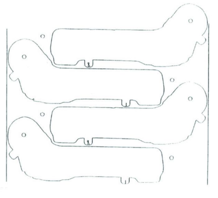 Another design consideration: cam accessibility. Cam operations in progressive dies usually are minimized to fit within the confines of the pitch length and carrier design. Cam operations in transfer dies can be designed for maximum accessibility and adjustment.