If a metalformer uses a press with the parameters specified above to apply a constant force of 1000 kN over a distance h of 5.6 mm, the energy used during forming is W = F x h= 5600 Nm. The press then is being used to the limits of its rated force and energy. If the same force were to act over a distance of only 3 mm, the energy expended is 3000 Nm, and the force of the press then is fully used, while the available energy is not completely used.
The situation is much more unfavorable if the rated flywheel energy of 5600 Nm is applied over a working distance of h = 3 mm. In this case, the effective force of the slide will be:
F = Wn/h = 5600 Nm/0.003m = 1867 kN.
As the maximum permissible press force is only 1000 kN, in this case the press is being severely overloaded. Although the flywheel slowdown is within normal limits and gives no indication of overloading, all elements subjected to the press force may be damaged, such as the press frame, slide and connection rods. Serious overloading often occurs when press forming is conducted using high forces over small distances, such as during blanking or coining. The danger is that such overloading may go undetected, which requires the use of overloading safety devices to protect the press.
Another form of overloading results from taking excessive energy from the flywheel, which can cause extremely high press forces to develop if the displacement during deformation is too small. However, if the energy is applied over a large displacement, this type of overload is much less dangerous. For example, if the press described above is brought to a stop during a working distance of h = 100 mm, the entire flywheel energy of W = 15,600 Nm is utilized. Assuming that no peak loads have occurred, the mean press force exerted is only F= w/h = 15,600 Nm/0.1 = 156 kN.
The press is, therefore, not overloaded although the flywheel has been brought to a standstill. In this case, only the drive motor suffers a large slowdown and it is necessary to use a press of a larger flywheel-energy capacity, although the permissible press force of 1000 kN is more than adequate. Overloads of this type occur more frequently if deformation is done over a large distance—during deep drawing, for example.
Types of Drive Systems
Eccentric or crank drive—For a long time, eccentric or crank-drive systems, were the only drive mechanism used in mechanical presses. The relatively
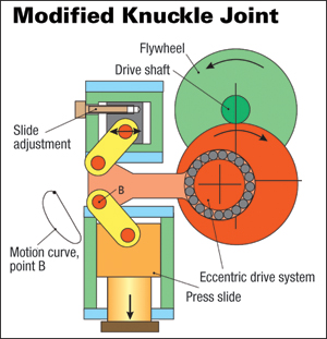 |
| Modified knuckle-joint drive systems can be either top- or
bottom-mounted. Particularly for solid forming, the modified top-drive
system, shown here, is popular. The fixed point of the modified
knuckle-joint is mounted in the press crown. While the upper joint
pivots around this fixed point, the lower joint describes the curved
path, as-illustrated. This results in a change of the stroke-vs.-time
characteristic of the slide, compared to the largely symmetrical
stroke-time curve of an eccentric drive system. |
high impact speed on die closure and the reduction of slide speed during forming are drawbacks that often preclude the use of this type of press for deep drawing at high stroke rates.
However, in presses with capacities to a nominal force of 5000 kN, such as universal or blanking presses, a crank drive is still the most effective system. This is especially true when using automated systems where the eccentric drive offers a good compromise between the required processing time and the time required for part transport. Even with the latest crossbar-transfer presses, eccentric-drive systems used in subsequent processing stations—after drawing—satisfy the requirements for system simplification.
Linkage drive—Attempting to maximize stroke rates using crank- or eccentric-drive systems requires increasing the slide speed. However, when deep drawing, ram speed typically must not exceed 0.4 to 0.5 m/sec. during deformation. A linkage-drive system can be designed for mechanical presses so that slide speed during drawing can be reduced by as much as half compared to an eccentric drive. The slide in a double-acting deep-drawing press, for example, is actuated using a specially designed linkage drive. This kinematic characteristic offers ideal conditions for deep drawing. The slide hits the blank softly, allowing it to build up high press forces right from the start of the drawing process, forming the part at a low, almost constant speed. In addition, this system ensures smooth transitions between the various portions of the slide motion. During deformation, the drive links are stretched to an almost extended position; clutch torque, the gear load and the decelerating and accelerating gear masses are between 20 and 30 percent less than with a comparable eccentric press. In the case of single-acting machines, for instance, reducing impact increases the service life of the dies, the draw cushion and the press itself.
This offers a number of important benefits in production. For the same nominal press force and slide stroke, a link-drive press can be loaded substantially earlier in the stroke, because the press-force displacement curve is steeper within the deformation range. Therefore, a linkage press has a more favorable force-displacement curve than does an eccentrically driven press. Without increasing the impact speed, it is possible to achieve an appreciable increase in the stroke rate and output. Due to the improved drawing conditions, a higher degree of product quality is achieved; even low-quality sheetmetal can be used with satisfactory results.
In addition, this system reduces stress on the die and the draw cushion and also on the clutch and brake. And, noise levels are reduced due to the lower impact speed of the slide and the quieter herringbone gears of the drive wheels.
In the case of large-panel transfer presses, the use of six- or eight-element linkage-drive systems is largely determined by deformation conditions, part movement and the overall structure of the presses. As a result, in the case of transfer presses with tri-axis transfer system, a six-element linkage-drive system often is used, representing the best possible compromise between optimum press geometry and manufacturing costs. In the case of crossbar transfer presses, either an eight-element linkage drive or a combination of linkage and eccentric drives is used to optimize the die-specific transfer movements.
Knuckle-joint drive—This design principle is applied primarily for coining. The knuckle-joint drive system consists of an eccentric or crank mechanism driving a knuckle-joint. The fixed joint and bed plate form a compact unit. The lower joint moves the press frame and acts as a slide to move the attached top die up and down. Due to the optimum force flow and the favorable configuration possibilities offered by the force-transmitting elements, a highly rigid design with very low deflection characteristics is achieved.
The knuckle-joint drive, with a relatively small connection-rod force, generates a large pressing force—with the same drive moment it is possible to achieve three to four times more force than with an eccentric press. Further, the slide speed in the region 30 to 40 deg. above BDC is appreciably lower. Both of these design features represent a particular advantage for coining, and for forming in a horizontal press.
By inserting an additional joint, the kinematic characteristics and the speed-vs.-stroke of the slide can be modified. Knuckle-joint and modified knuckle-joint drive systems can be either top- or bottom-mounted. Particularly for solid forming, the modified top-drive system is popular. The fixed point of the modified knuckle-joint is mounted in the press crown. While the upper joint pivots around this fixed point, the lower joint describes a curved path. This results in a change of the stroke-vs.-time characteristic of the slide, compared to the largely symmetrical stroke-time curve of the eccentric drive system. This curve can be altered by modifying the arrangement of the joints, or by integrating an additional joint.
As a rule, it is desirable to reduce the slide velocity during deformation, reducing impact and the pressing speed of the slide. Using this principle, the slide displacement available for deformation can be increased by three or four times than when using eccentric presses with a comparable drive torque.
Blankholder drive—Sometimes used in double-acting deep-draw presses, this drive is a special case. The required standstill of the blankholder during deep drawing is achieved in this type of machine by superimposing a double knuckle-joint system with an eccentric or linkage drive of the slide. The standstill of the blankholder represents a crank angle of between 90 and 130 deg., with a maximum residual movement of 0.5 mm. This residual movement does not, however, influence the deep-drawing process because the blankholder overload safeguard acts as a storage system and the elastic deflection of the entire press—a few millimeters—has an overriding effect. The slide drive, the blankholder drive and wheel gear are integrated in the press crown.
Drive Motor and Flywheel
In larger-scale presses, the main drive system usually is powered by DC motors, primarily to provide a large stroking rate. Frequency-controlled three-phase motors offer an alternative, particularly where a high-protection class rating is called for. The output of a press, determined by force, slide displacement and speed, including lost energy, is provided by the main motor. Periodically occurring load peaks are compensated by the flywheel, which stores energy. The highly elastic DC drive system can compensate for a drop of the flywheel speed of as much as 20 percent in every press stroke and can replace the consumed energy by acceleration of the flywheel prior to the subsequent stroke.
Useful energy also should be available during setup with a reduced stroke rate, 5 strokes/min. for example. In this case, a speed drop of 50 percent is admissible. An important criterion in configuring the energy balance is to ensure a short run-up time. Running up a large-panel press from its minimum to maximum production stroke rate generally takes less than 1 min. under load.
Due to the required useful energy and the permissible flywheel slowdown of 20 percent, the flywheel generally is designed to operate under the most energy-consuming condition—in the lower stroking range of the press. Although a high flywheel speed is beneficial, this is limited by the admissible speed of the clutch, brake and flywheel itself.
Clutch and Brake
Mechanical presses use a clutch to transmit motor and flywheel torque to the gear shaft. After clutch release, a brake decelerates the slide, the top die and the gear. Particularly when working in single-stroke mode, the masses in translational or rotational motion must be brought to a standstill after every stroke within an extremely short time: 200 to 300 msec. for large-panel presses, 100 to 150 msec. in universal presses. Conversely, after engaging the clutch, the same masses must be accelerated from zero to operating speed.
For safety reasons, braking is generated mechanically by spring power. Clutch torque is calculated from the nominal press force and the required working distance, generally 13 to 25 mm above BDC.
Pneumatic single-disk clutch and brake combinations with minimum
 |
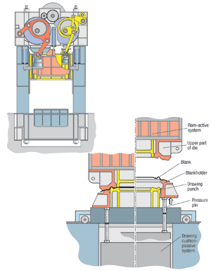
| Press slide weight is compensated for by a slide counterbalance system. Pneumatic cylinders balance the weight of all moving parts—joints, connecting rods, slide and upper die. As a result, the drive system is largely free of gravity forces—no stresses act on the slide adjustment, and there is an additional safeguard against downward travel of the slide caused by gravity. Pneumatic weight compensation guarantees low-noise vibration-free operation, smooth loading of the motor and short braking distances. |
rotating masses have been used for decades. Pneumatic control systems with safety valves and damping devices are reasonable in cost and generally comply with requirements. One of the problems of pneumatic systems, however, is the limited switching frequency of single-stroke presses and the environmental damage caused by wear to the clutch and brake. In order to eliminate these drawbacks, hydraulic systems have become more popular. With the aid of cooling systems, these units permit far higher switching loads per time and are practically immune to wear. In single-stroke presses, separate units that permit switching frequencies to 30/min. have been used to permit more effective control and to avoid overshooting and undershooting by the clutch and brake. Large-panel transfer presses use clutch-brake combinations based on sintered disk sets with as many as 20 friction surfaces, and transmission torque levels to 500,000 Nm.
The compact drive system used in smaller mechanical presses consists of a flywheel, clutch, brake and planetary gear in a complete unit. Such a system achieves a particularly high level of efficiency with an extremely low moment of inertia and small braking angle, coupled with a long service life and low maintenance costs. The electric motor drives the eccentric shaft via a flywheel, a clutch-brake combination—either hydraulically or pneumatically actuated, and a high-performance planetary gear. This setup eliminates the need for the reducing gear generally required for universal presses. Compact drive systems using a hydraulic clutch-brake combination are particularly environmentally friendly, as they produce no abraded particles and run at an extremely low noise level.
Longitudinal and Transverse Shaft Drive
The design of a mechanical press is determined mainly by the arrangement of the drive shafts and axles, and by the number of pressure points of the connecting rod on the slide. The term longitudinal or transverse shaft drive is defined by the arrangement of the drive shafts relative to the front of the press, where the press operator stands.
A longitudinal-shaft drive is used mainly in single-acting one- and two-point presses with eccentric drive systems. These generally are blanking and universal presses in the lower force range to 8000 kN. This classical drive arrangement also is used in long and narrow transfer presses where two to six pressure points or connecting rods are located in the longitudinal direction. The connecting rods are driven by a continuous drive shaft. Transfer presses are designed with nominal pressing forces between 1000 and 35,000 kN, and have as many as four pairs of uprights and three slides.
The connecting rods are arranged in the area of the uprights and tie rods to minimize bending stress on the press crown. This leaves the top of the workstations in the slide free for ejection functions. For simpler production and assembly in larger-scale transfer presses, the longitudinal shaft drive also is replaced by a transverse-shaft drive system. Knuckle-joint presses with single-point drive, covering a force range of 1500 to 16,000 kN, represent another special construction.
The transverse-shaft press is designed to have one-, two- or four-point connections and pressing forces of 1600 to 20,000 kN. This design permits a greater bed depth, a longer stroke and the use of a joint system. Double-acting deep-drawing presses are only available in this configuration.
Slide Adjustment, Overload Protection and Counterbalance
In presses, pressure points with a slide adjustment to 600 mm are used in the main spindle to allow adjustment of shut height. In universal and transfer presses, slide-adjustment distances of 150 mm are sufficient; and, pressure points with a low overall height prove useful. Using brake motors and worm gears, stampers can attain speeds of 60 mm/min. With multiple-stage presses, used for solid forming, wedge adjustments are frequently used in the die set or at the slide clamping plate, to achieve high stiffness. Here, slide adjustment is unnecessary.
Nominal press force is limited and safeguarded by a hydraulic overload safety device in the slide. If this press force is exceeded, the pressure exerted on a hydraulic cushion integrated into the pressure point is quickly relieved, allowing an overload displacement. For blankholders used in double-acting mechanical presses, the overload safety function is coupled to the adjustment function of the blankholder force. The overload safety function is activated only when the deflection of the four blankholder pressure points exceeds a permissible magnitude of approximately 3 mm. The safety function is actuated by an air-hydraulic pressure scale. By changing the compressed-air setting, blankholder force can be adjusted to the requirements of the die at the four pressure points, within a range of 40 to 100 percent.
Slide weight is compensated for by a slide counterbalance system. Pneumatic cylinders balance the weight of all moving parts—joints, connecting rods, slide and upper die. As a result, the drive system is largely free of gravity forces—no stresses act on the slide adjustment, and there is an additional safeguard against downward travel of the slide caused by gravity. Pneumatic weight compensation guarantees low-noise vibration-free operation, smooth loading of the motor and short braking distances.
To counterbalance weights to 200 tons at 10-bar air pressure, cylinder size must be as great as 900-mm dia. Long slide strokes, to 1300 mm, and permissible pressure spikes to 25 percent require substantial surge tanks. The arrangement of cylinders and tanks depends on the type of press and safety issues. In the case of counterbalance cylinders not externally enclosed, double piston rods often are required to safeguard against the risk of breakage. Conversely, integrating the system into the press crown makes this additional safety feature unnecessary.
With every die change, the weight-compensation system must be automatically adjusted to the new die weights. Program-controlled automatic systems used in transfer presses automatically set the program inherent pressure value when changing dies, to minimize setup time.
Pneumatic & Hydraulic Systems
The major pneumatic functions of mechanical presses are the clutch, brake, flywheel brake, slide counterbalance, slide cushion and bed cushion. With transfer presses, pneumatic functions also include the application of air pressure to the transfer cam followers and workpiece transport by suction cups. Large volumes of air require compressed air tanks with a monitoring safety function and drainage system. The maximum pneumatic pressure is generally
6 bar (90 psi), although high-pressure networks or compressors producing a maximum of 16 bar (230 psi) increasingly find use.
The use of hydraulics in mechanical-press construction is relatively minimal, typically restricted to the hydraulic overload safeguard, raising the moving bolster and hydraulic die-clamping systems. All of these functions generally are supplied from a central hydraulic unit.
With transfer presses, additional hydraulic functions include engagement of the clutch between the press and transfer-drive systems, and the comprehensive system of scrap-ejection flaps. In addition, hydraulics may drive various clamping and locking devices around the press. The most important function in mechanical presses—engaging and braking the slide drive system—is increasingly being accomplished via hydraulics. The use of hydraulics permits higher switching frequencies in single presses, and is more environmentally friendly in terms of noise and air pollution. The clutch and brake are supplied by a central hydraulic unit equipped with a cooling system. Also required: A dual-channel safety control with regulated damping facility and pressure filtration to 10 µm.
The increased use of deep drawing with single-acting presses places stringent demands on the blankholding function and, therefore, the draw cushion in the press bed, particularly with large panel presses. Multiple-point bed cushions with pressure control capability then are only possible using a complex servo hydraulic system. This requires separate supply units with oil tank, pump outputs of approximately 150 kW and oil-flow rates of approximately 1000 l/min. for the draw cushion.
Keeping Presses Well Lubricated
The complex lubrication systems used to supply the lubrication points of mechanical presses can be simplified by using valve blocks. The typical lubrication system comprises parallel-switching progressive distributors. To allocate the required quantity of lubricant, the system includes volume controllers, dividers and similar elements. The flow of oil is monitored at the distributor blocks and, to ensure optimum operating conditions, a control system regulates lubricant temperature within a narrow bandwidth, by using auxiliary heating and cooling functions.
To maximize operating safety, complex production installations for metalforming als include twin supply-unit elements, such as pumps and filters, so that if one element fails there is no need to interrupt production, as the second system cuts in automatically. Also, maintaining or exchanging the defective system does not interrupt production.
In smaller presses, and in particular bottom-drive knuckle-joint presses, central lubrication systems with multiple-circuit geared pumps find use. These systems continuously supply lubricant to as many as 20 main lubrication points. During the short swivel movements executed by the thrust elements and joints, a constant flow of lubricant is available even under varying resistance levels in the individual user and supply lines. MF
Industry-Related Terms: Forming,
Lines,
Nominal,
Plate,
Ram,
Run,
Scale,
Shut Height,
Stroke,
Torque,
Transfer,
Form,
Drawing,
Bed,
Bending,
Blanking,
Cam,
Case,
Center,
Coining,
Die,
Draw,
BlankView Glossary of Metalforming Terms
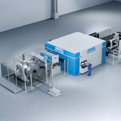
See also: Andritz Schuler
Technologies: Stamping Presses