


The Past, Present and Future of Die Design
February 1, 2011Comments
Back in the day, high-tech die design was an electric eraser to go along with your drafting machine. By the early '90s, 2D CAD programs became prevalent, as did specialized die-design-specific software packages for these programs. Where are we today? Read on...
 |
To build more complex dies, an experienced die designer, who in most cases was previously a tool and die maker, would sometimes provide drawings developed on a drafting machine and drawing board; for really complex dies, the designer would even add some dimensions to his design. As digital readouts started appearing on Bridgeport mills, more components were detailed on the drawing board, typically of perishable components.
In the late 1980s and into the early 1990s, the vast majority of die design moved from the drawing board to 2D CAD. During this same timeframe, U.S. die designers had at their disposal a couple of different die-design software packages that operated within AutoCad. Those that added these specialized software packages to their 2D CAD software enjoyed significant increases in productivity.
Since that time, die making has gradually evolved into much more of an assembly-line process. As a result, tool and die makers have become less prepared to become die designers, and less able to create dies without a design provided to them.
3D CAD Goes Mainstream
In 1995, the first parametric-based 3D CAD package able to run on a personal computer was released. The software only offered solid-modeling functionality, without any surfacing or assembly capability. Over time it was developed to include these capabilities, and became known as a hybrid system.
2D CAD is comprised primarily of lines and circles, so it matured rapidly; parametric-based 3D CAD took longer to evolve. Over the past decade, 3D CAD software has become common in tool and die companies. Why? Productivity—it is practically unheard of for any product design to be developed using 2D as opposed to 3D software. Therefore, there are solid or surface models available for most of the parts for which dies will be designed.
Die-Design Timesavers
Designers find that when adding specialized 3D die-design software to their 3D CAD software, they can dramatically reduce design time—by as much 30 to 50 percent depending on die size and complexity.
One immediate timesaver is the ability to flatten complex-shaped 3D stamped parts using finite-element-analysis (FEA) software. Some companies include FEA in their die-design software packages, while others offer it as an option. And, some FEA software goes beyond flattening and can automatically generate models for the intermediate part forms based on user input.
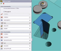 |
| In less than 5 min., an insert can be added to a plate along with a shim or backup plate, with proper clearances for both, along with various corner treatments for the cavity in the plate receiving the insert. |
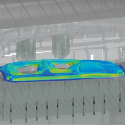
While these FEA tools prove very handy, they will not replace dedicated FEA forming-simulation software packages, which prove particularly useful when working with complex stamped parts. These dedicated FEA programs allow the designer to simulate forming and predict numerous outcomes including wrinkling, failure and springback—tasks that challenge even the most experienced tool and die maker—with incredible accuracy.
When designing dies for parts that have only linear bends, often the 3D CAD package alone cannot unbend the parts, but the die-design unbending software can. When the software unbends a part, it also can automatically calculate each bend’s k-factor. After parts are flattened or unbent, the software then can generate a strip layout, with punches, often in just a few minutes.

 Webinar