The Latest in Die Design and Simulation Software
March 1, 2019Comments
Check out the newest offerings to help ease die design and build, and ensure that tooling performs as planned in the press, producing the right part features hit after hit. In April's MetalForming, read how these software products help users meet an assortment of design, build and use challenges.
New Release: Integration from Quoting to Design to Manufacturing
Cimatron 14
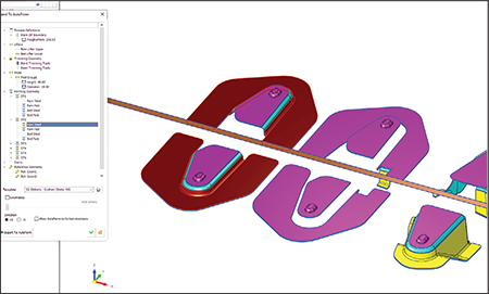 |
| Cimatron strip design with the new Export to ProgSim dialog allows designers to validate a design before manufacturing, thus reducing iterations. |
For example, new integration of AutoForm Prog-Sim enables users to reduce the number of iterations. Typically, the die design process consists of several production iterations of the tool or the blank in order to analyze springback effect, trim optimization and other aspects that could impact the desired result. Cimatron 14 with AutoForm Prog-Sim reduces iterations and allows the designer to validate a design before manufacturing the die. Users now can load a complete strip-design project created in Cimatron directly into the AutoForm environment, run the simulation in one continuous process, and once the result is available, read, manage and display the results in Cimatron.
Also, Cimatron 14 reportedly includes a new capability to easily define and create addendum faces between the blank faces and the binder. This is especially beneficial in transfer and regular die design where large parts transfer between multiple presses to shells, tube applications, frames and structural components.
And, Fuzzy Offset, a robust surface-offset feature, enables users to easily create an approximate smooth offset surface out of a complex skin surface. The Fuzzy Offset feature also offers a powerful option for die casting and mold design, according to company officials.
Die System Simulation Software with New Interface, Set-Up-Time Reduction
Dynaform Version 6.0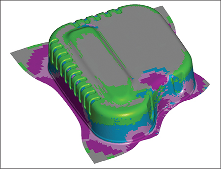
With an all-new user interface, the Dynaform 6.0 die system simulation software enables users to quickly conduct sheet metal stamping simulations to estimate the blank cost and formability of stamping parts via guided process wizards.
Engineering Technology Associates, Inc. (ETA) offers the latest release of its LS-Dyna-based, Dynaform Version 6.0 die system simulation software. Dynaform 6.0 offers an all-new graphic user interface with combined pre- and post-processing capabilities. Users quickly can conduct sheet metal stamping simulations to estimate the blank cost and formability of stamping parts using guided process wizards.
In addition, new features are included, such as a simulation data manager and Microsoft PowerPoint-based automatic report generation. The new software also consists of simplified as well as advanced customized features to reduce set-up time.“Dynaform 6.0 will improve the efficiency and productivity of stamping engineers with no prior experience in stamping simulation,” says Dr. Akbar Farahani, CEO of ETA.
Enhanced Reverse Engineering
VISI 2019 R1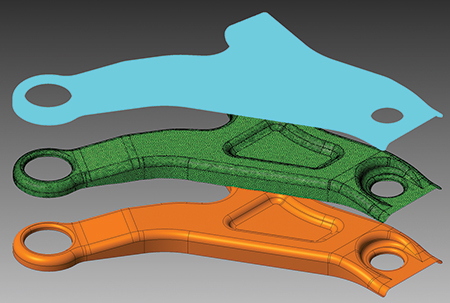
VISI now has the ability for a points cloud from a scanning or measuring machine to be loaded either directly or indirectly, and the relative mesh can be created by setting different options for refining and smoothing. This capability eases reverse-engineering tasks.
TST Tooling Software announces major software enhancements in the latest release of VISI software, including several for reverse engineering, along with a range of new and improved CAD/CAM functions for the progressive-die market.
As part of a larger collaboration project for reverse engineering and casting, VISI 2019 R1 introduces an extended direct interface to multiple portable measuring arms and Leica scanning devices from Hexagon. These enhancements, together with the dedicated module update, provides a reverse-engineering solution as well as the ability to generate casting and stock models from VISI’s existing modeling and machining environment.
With these updates, VISI now has the ability for a points cloud to be loaded either directly or indirectly, and the relative mesh can be created by setting different options for refining and smoothing. Surfaces can be created automatically or semi-automatically by extracting different key geometrical references from the refined mesh. Scan data, stock or reference casting mesh models easily can be aligned to the original geometrical CAD model using dedicated commands to allow comparisons, gap analysis and optimized toolpath processes, according to company officials.
Also, the VISI blanking process has been enhanced. By simply defining the relative force to apply, faces can be set on the model affected by the pressure pad. This allows the material to flow based on the applied force on the pressure pad. And, users now can set constraints to simulate the effect of a uniformly distributed blankholder force. Now it is possible to define a friction value and the force value to be applied for the blanking phase. This leads to a more accurate blanking process, which provides additional support to the user during die design.


 Webinar