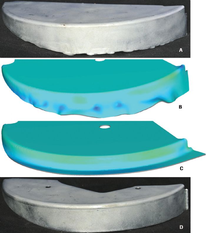
“Before the discussion even starts on use of newer tool materials,” Bell says, “we try to evaluate a metal former’s ability to track, quantify and trace performance, failures and process elements within the tool. The most sophisticated automotive OEMs will remove a die from the press and scan a detail, then compare the scan-detail dimensions with the original detail and determine where a tool is breaking down. Then they’ll take the data to determine why the detail failed and how they can correct it. At the other end of the spectrum, a Tier One supplier under tremendous time pressure just runs and runs the tooling until a detail breaks, and then installs another until that one breaks. There’s no follow up or awareness as to solving the problem.
“Now, in the last 5 to 10 yr.,” Bell adds, “I will say that the industry has improved greatly in problem-solving tool problems. But, there’s still the thought that during die design, ‘if it’s a trim section, let’s use S7; if it’s a form section, let’s use D2; and unless it gives us a headache, we'll keep using it.’”
Innovation in Shearing, Press Building, Hot Stamping
More proactive are material processors tasked with slitting or blanking, according to Bell, who better identify what materials best perform in cutoff tools and have implemented improvements.
And, with stamping presses providing greater force to deal with the newer super-high-strength materials, forged bolster blocks (Groditz produces such blocks) find increased use as an alternative to more fragile cast constructions in press builds.
Hot stamping represents an area, notes Bell, seeing a rapid evolution in tool-material technology and application. H13, for example, commonly used in diecasting applications, also has found a home in hot stamping. Offshoots of H13 with higher alloy content, he reports, have made inroads as well.
“The hot stamping process is so unique: placing a heated blank into a die, shaping it at a rapid rate and trying to achieve the final needed dimensions,” Bell says. “The die material involves three considerations during hot stamping: conductivity, or time needed to heat and cool the material; hot wear, or how much wear will occur at higher temperatures; and conformal cooling, the ability to run cooling lines through the die and dissipate the heat.
“Conductivity doesn’t really enter the conversation in cold stamping, but in hot stamping, it’s a huge factor in how quickly a line can cycle,” Bell continues. “The die must cool and recover before it can cycle again. And, from a metallurgy standing, running a die super hot can cause it to anneal and soften. As for hot wear, the big hot stampers study this and much of the data is proprietary as to how these materials wear at high temperatures.”
Additive manufacturing (AM) may provide an answer to cooling challenges, as the process allows for manufacturing conformal-cooling lines directly into the die.
“Imagine a hot stamping die section about half the size of desk, which is pretty large,” Bell says. “Placing conformal-cooling lines within that die to cool the die quickly between cycles gains huge efficiencies.”
The limitation here: insert size.
“AM typically can’t produce inserts in large sizes, as AM-machine work envelopes are relatively small,” Bell offers. “But that’s changing. As soon as I say that the envelopes are too small, we’ll probably see a machine with an envelope size capable of producing a die block.”
Die Design/Sim. Automation Combats Experience Loss
As with other facets of manufacturing, die design, build and repair have been challenged by the loss of experienced tool and die professionals and fewer entrants into the trade. This has caused developers of incremental forming-simulation software to team up with developers of parametric die-design software, according to Ray Proeber, president of Accurate Die Design Software.
“Customers commonly require incremental forming simulation on parts prior to die build,” Proeber says. “Developers of die design-and forming-simulation software recognize the need to perform simulation more quickly and make it an integral part of the die-development process.”
The result: affordable and user-friendly incremental forming-simulation software running inside of parametric die-design software.
“The forming-simulation software no longer is disconnected from the die-design software,” Proeber explains. “Better yet, incremental forming simulation can be run at the initial strip-layout stage of die design. This not only eliminates finding mistakes during tryout after designing and building the die, but also during die design itself, as the formability information needed is known before design begins.”
Similarly, Proeber sees integration of more tools into die-design software to automate the process and to perform mechanical debugging of a die prior to ordering die-build material.
“The die can be run in a virtual forming-simulation tryout press while still at the strip-layout stage via incremental forming-simulation software,” says Proeber, “and after all of the actual tooling is designed around the strip layout, the die runs in a virtual motion-simulation press to find mechanical mistakes in the die itself.”
Automation within die-design software further eliminates mistakes, according to Proeber. One example: Automatic creation of the bill of materials within minutes.
“Such automation speeds die design, build and tryout by eliminating the time needed to perform such chores as well as to identify mistakes and fix them prior to build,” he says.
Previously, with strip-feeding and formability problems addressed in a tryout press, die designers would begin developing the flat blank. Always a large consumer of press time, notes Proeber, flat-blank development often required anywhere from four to 12 times in and out of the tryout press, with each blank iteration requiring new measurements and the creation of new flat blanks.
“Today, incremental forming-simulation software can develop—automatically and virtually—the flat-blank shape before wire-EDMing of punches and die blocks, and before the die ever enters the tryout press,” Proeber says. “Die builders that design, build and try out dies find a much quicker and smoother experience from start to finish through this new integration of incremental forming-simulation software into their die-design software.”
Tool Coatings Keeping Pace
There’s a continuing need for high-performance tool coatings to meet the needs of metal formers tasked with cutting and shaping higher-strength materials including stainless steels and advanced high-strength steels, reports David Bell, president of Phygen Coatings Inc., Minneapolis, MN.
“All of these materials place increasing demands on tool coatings to reduce friction and eliminate metal pickup and galling,” Bell tells MetalForming. “Sectors increasingly taking advantage of tool-coating capabilities include those tasked with producing the highest-precision parts, such as ammunition makers, and also appliance makers, which often push the limits in drawing stainless steel.”
Those building, servicing and using stamping tooling should be aware of the various coating treatments available and consult with coating suppliers to ensure that the coatings can manage the challenges of specific forming applications. Proper coatings, Phygen’s Bell offers, extend the range of successful forming capabilities while extending tool life.
“For example, a lower-temperature coating process that Phygen employs,” he says, “deposits a dense nanocrystal coating with particles sized from 14 to 40 nanometers, with this particle size enhancing adhesion.”
Duplex coating, notes Bell, is another development area that can help improve coating adhesion. Here, application of plasma ion nitriding precedes the coating in order to achieve an optimal base depth.
“This enhances the rigidity support and adhesion of the coating placed on top,” he says.
Beyond the technical specifics of various coatings available to the metal-stamping community are general issues of which metal formers should be aware.
“The movement toward a greener economy adds importance to the use of high-performance tool coatings,” says Bell. “As water-based lubricants become more common, high-performance surface enhancement will be needed to attain forming success and needed tool life.”
And, be sure to mind the substrate, offers Bell.
“We see an opportunity for metal formers in what we refer to as D2 upgrade materials,” he says. “There’s a desire to solve the challenge of common D2 die material—large carbide particles that prove unfriendly for polishing. Consider upgrading the die material if you’re looking for extreme performance.”
Mind Feed-System Settings
Beyond die materials and coatings, metal formers greatly affect tool performance in the press. This includes feed-system setting during job setup. To ensure proper performance of tooling in the stamping press, avoid inconsistencies in product quality, and minimize the likelihood of tool breakage or premature tool wear, stampers should strive for proper setting of the feed system.
That’s the word from Pete Ulintz, technical director for the Precision Metalforming Association and author of the monthly Tooling By Design column in MetalForming magazine.
“Setting the feed system properly, including the pilot-release function, often proves challenging for the die setter, yet is critical for successful progressive die stamping,” Ulintz offers. “While suppliers can provide highly accurate feed systems that practically eliminate the need for pilots in the die, many older feeds will overwork pilots beyond their original design intent due to improper setting of feeds.”
The pilot release, also known as the feed release, allows the pilots in the die to accurately position and register the strip. For the pilots to position the strip correctly, according to Ulintz, the upper feed roll must open (lift) immediately after the tip of the pilot enters the strip. If the feed roll opens too early, the strip could pull out of position due to the weight of the material in the feed loop between the feeder and the coil.
In addition, if the feed roll closes too soon, the feed length will appear excessively long. This holds especially true, Ulintz explains, for progressive dies that require long stock-lifter travel to clear working stations in the die.
“The downward travel of the coil stock during die closure pulls additional material through the feed unit while the feed roll remains open,” he says. “Should the feed roll close before the stock lifters return to their full-up position, extra material becomes trapped between the die and feed. This extra material pushes the strip forward when the pilots exit the strip, causing the next feed progression to appear long.”
Press operators must take care to assess this issue properly to avoid problems.
“Incorrect identification of this problem,” Ulintz says, “may cause the press operator to begin making program adjustments to the feed to compensate for timing errors with the pilot release.” MF
Industry-Related Terms: Blank,
Blanking,
Conductivity,
Die,
Drawing,
Feed Unit,
Form,
Forming,
Insert,
Lines,
Nitriding,
Polishing,
Run,
Shearing,
Spectrum,
Substrate,
SurfaceView Glossary of Metalforming Terms
See also: PHYGEN, Accurate Die Design Software, Inc., Groditz Steel North America
Technologies: Finishing, Materials, Software
 “I remember 20 years ago when the industry started incorporating high-strength, low-alloy stamping material, and that evolved into advanced high-strength steel,” recalls Tom Bell, vice president Americas for Groditz Steel North America, Deer Park, IL. “Now, we hear about 1200-MPa material and higher—steel makers have developed much stronger and much thinner steels.”


