3D Technologies for Stamping Die Design
August 1, 2014Comments
Understand the differences between parametric and direct modeling to find the right method, or combination of methods, for the die-design job at hand.
 Metal stampers have a variety of software tools available to them: design tools (CAD), simulation and analysis tools (CAE), and manufacturing tools (CAM). On the design side, the most often used design tool is referred to as parametric or history-based modeling. Another technology quickly gaining acceptance: direct modeling.
A Brief History Lesson
In the early days of mechanical CAD, software developers selected one of two techniques for developing geometry at the accuracy levels required to support mechanical design: construct solid geometry (CSG), and boundary representation (b-rep). The CSG technique to create and modify geometry uses primitives such as cylinders, blocks and cones with Boolean operations such as union, intersection and combines. The primitives and Booleans were organized in a structured tree. To modify the model, an existing primitive or Boolean, or both, could be edited or replaced. The designer could replay or regenerate the tree structure, resulting in a different 3D object.
The b-rep technique of representing 3D shapes describes the connectivity (topology) of vertices, edges and surface boundaries to form faces, which connect to form solid bodies. It provided flexibility in the types of geometry described, but proved somewhat rigid when it came to editing the geometry. On the other hand, CSG traditionally has proved somewhat limited in the types of geometry that could be represented, while providing editing flexibility.
In the early to mid-1980s, work by Sam Geisberg (a Russian immigrant and mathematics genius) and others sought to combine the CSG tree structure with b-rep primitives, so that the b-rep primitives could be created with sketches. Any primitive shape could be defined and used in the model creation. These sketches were parametrically controlled and managed as elements of the feature tree. As such, the resulting b-rep primitives (features) were parametrically controlled. This combined the robustness of b-rep with the editability of CSG and created parametric modeling, also called history-based or feature-based modeling.
As parametric modeling became the industry standard for 3D mechanical CAD, Hewlett Packard worked to develop a different to make b-rep more flexible. It sought to remove the need to understand design intent before beginning the modeling process. Staying with pure b-rep, HP developers found s to make the software more flexible, and their development work led to the creation of dynamic (or direct) modeling. (The organization responsible for mechanical CAD at HP separated from HP in 2000 and became CoCreate Software, purchased by PTC in 2007).
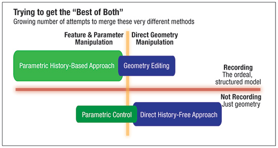
Fig. 1
With direct modeling, any 3D geometry can be fully manipulated and integrated regardless of how it was created, or the CAD tool used. This reduces the need for modeling standards, improves interoperability and reduces the amount of model recreation.

 Webinar