Additionally, ensure that the clutch air pressure is set to the manufacturer’s specification. Higher-than-recommended pressure is unnecessary and increases the mass of air that must be evacuated from the clutch to stop the press. For a press equipped with an air-counterbalance system, ensure that the pressure is properly set for the upper-die weight. Counterbalance pressure set too high or too low extends the press-stopping time.
Finally, check the feed advance timing for each die and ensure that the feeder starts as soon as the die opens. Feed progression usually is the last thing that a die-protection system must verify before a stroke initiates. The sooner the feed starts, the sooner it will end, giving die protection the maximum time to stop the press before the critical angle.
Calculate the Critical Angle
The critical angle is the last point in the press’ crankshaft rotation to signal an immediate stop and have the press stop before die closure. Many factors affect the critical angle, including press speed, stopping time, tooling design and control-response time.
Programming die-protection control requires knowing the critical angle for the die. To determine this angle, first observe the die-closure angle—usually where the pilots begin to enter the strip. Create a test program in the die-protection control consisting of a single cyclic (green) sensor with a ready window that ends at 0 deg.; then disable the sensors, run the press to its operating speed and enable the sensors on-the-fly. The die-protection controller will initiate a stop signal at top dead center. Observe the angle at which the ram stops—the stopping angle, or the number of degrees that the crankshaft moves after a stop signal initiates. Subtract the stopping angle from the die-closure angle to calculate the critical angle. Repeat this calculation for every die in every press.
When programming the die-protection control, ensure that all monitored events occur before the critical angle to prevent die damage.
Use Die-Mounted Junction Boxes
Die-protection systems monitor press-mounted sensors (such as those that detect material buckle and end of material) and die-mounted sensors (feed, part ejection, stripper position, etc.).
Press-mounted sensors stay with the press and can be hard-wired to the die-protection controller. Die-mounted sensors must be connected and disconnected from the control during each die’s loading and unloading. Most die-protection systems are equipped with a sensor interface that is usually installed on the press column or frame near the die opening.
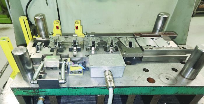
Die-mounted sensors can be connected to the interface in two ways: They can connect individually, where each sensor is equipped with a connector on its cable that plugs into the appropriate input on the sensor interface at run time—or collectively, where all of the die-mounted sensors wire to a junction box on the die, which connects to the sensor interface with a single cable.
Sensors last longer if installed within die-mounted junction boxes. Sensors connected individually require a cable with sufficient length to reach the sensor interface. Most electronic sensors come with 2-m cables. For a die not in use, the individual sensor cables usually are coiled up and stored with the die. At run time, the operator must untangle the sensor cables and plug each one into the correct input. The repeated coiling/uncoiling of the cable will cause it to fail. Most electronic sensors have permanently attached cables; when the cable breaks, the sensor must be replaced.
Die-mounted junction boxes protect the sensor cables, which are permanently wired to a terminal strip in the box, with all of the sensors connected to the interface through a single, large cable. Because this cable stays with the press, it need not be wrapped for storage; it usually rests on a hook when not in use. If the collective cable does fail, it can be replaced without having to replace sensors.
Other benefits to this approach add value. Sensor wiring to the junction box is direct, thus no long cables are attached to the die that can be damaged during handling or maintenance. Also, with a single cable, all sensors automatically connect to the correct inputs, eliminating the possibility of wiring errors.
Select Sensors Designed for the Environment
While selecting the correct sensor does not guarantee proper performance, it is possible to select a sensor that will fail in a stamping environment with certainty. This happens when selecting a sensor with an insufficient environmental rating. This important specification goes by several names, including:
- Enclosure rating (or “enclosure”)
- Degree of protection (or “protection”)
- Environmental rating
- Protection rating.
 The specification usually refers to an ingress protection (IP) rating. The IP rating system classifies the degree of protection that electrical-device enclosures provide. It consists of a two-digit rating whereby a higher number indicates a better degree of protection. The first digit runs from 0 to 6 and indicates the degree of protection against solid foreign objects such as fingers, dirt and dust. The chart to the right summarizes the first digit ratings:
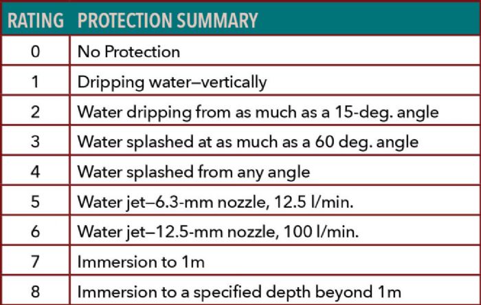
 The second digit can range from 0 to 8 and indicates the degree of protection against harmful ingress of water (liquid). The chart to the right summarizes the first digit ratings:
Any sensor for in-die use should have an IP-67 rating—dust-tight and protected against immersion in water to a depth of 1 m. An IP-68-rated sensor is unnecessary because it is unlikely that a stamping job will operate while submerged deeper than 1 m.
Theoretically, a sensor with an IP-66 rating should stand up to a stamping environment; however, the water jet test used to verify the rating has a short (3 min.) duration. Because dies in a stamping application are exposed to lubricant longer than 3 min., the lubricant can seep into the sensor, causing premature failure.
Following these best practices guidelines will help build the foundation for a successful die-protection program. MF
Press Controls and Sensors Series, Part 2: Pairing Sensor Types with the Problems They Address
Press Controls and Sensors Series, Part 4: Die-Protection Troubleshooting: Three Cases Explored
View Glossary of Metalforming Terms
See also: Wintriss Controls Group LLC
Technologies: Sensing/Electronics/IOT
Comments
Must be logged in to post a comment. Sign in or Create an Account
Ken R. THU, SEP 5, 2024 @ 4:44 PM
Hey I know that die.. ;)
 Sensing/Electronics/IOT
Prime Controls’ DS-Flex—a Configurable, Versatile Double-She...
December 30, 2024


 The primary goal of die protection is to detect problems and stop the press before the die closes. Such safety systems prove most effective when they’re provided with sufficient time to stop the press. Before embarking on a die-protection program, ensure optimization of the press’ stopping time. Performing regular brake maintenance is as obvious as it is essential. The press’ plumbing causes most of the remaining, less obvious stopping-time inefficiencies.
