Cutting Clearance
May 1, 2008Comments
Perhaps the most important requirement of any die operation is the proper alignment between all of the working components. In stamping operations, accurate alignment is necessary to maintain proper clearances between punch and die steels. Cutting, piercing and trimming operations require cutting clearances held within close limits. Because most stamping features are not symmetrical or totally round, cutting clearance usually is measured at one side of the cutting profile and specified as a “per-side” clearance. The amount of clearance applied to the cutting process and the quality of the cutting steels directly affect the quality of the sheared-edge surface.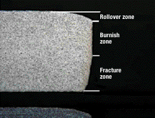
Fig. 1
Depending on the hardness and thickness of the material being cut, the ideal clearance can vary anywhere from 5 to 20 percent per side. Burr size, die rollover, burnish band and fracture zones are commonly used to characterize the quality of the shear edge. The image in Fig. 1 exemplifies a quality sheared edge exhibiting these characteristics (SAE paper 2007-01-0340, Konieczny, et al).
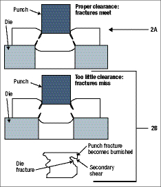 |
| Fig. 2 |
When the cutting clearances are small, press and die alignment become very critical. If this alignment is not maintained properly the punch and die details may contact each other and the cutting edges may be damaged. In addition, an edge defect known as secondary shear—sometimes referred to as a double-break —often will occur. Secondary shear results when the stamping fracture-zone angles from the punch edge and die edge do not meet. As a result, an additional band of material is sheared, producing a second burnish zone as the two fracture zones try to join (Fig. 2B); thus the term secondary shear. Small cutting clearances also require greater punching forces and cause greater punch wear, due to abrasion, as the pierced material grips firmly around the punch. As a result, increased stripping forces are needed to extract the punch.
Larger cutting clearances make press and die alignment less critical and also require less cutting and stripping forces. But if the cutting clearance becomes too great, extreme rollover occurs and undesirable burrs develop. In extreme cases, the material may actually tear or break open in the rollover zone if the surface is stretched beyond its ultimate tensile strength (Fig. 3; Eary and Reed). Soft, thick metals will sometimes extrude a thick heavy burr into the large cutting clearance gap.
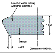 |
| Fig. 3 |