An additional factor during the design phase is computing the compensation needed for factors such as twist and springback.
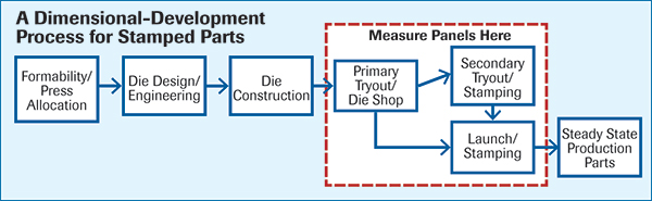
After completing the die-design stage, the die-build process shifts from the virtual world to the real world. Then the die shop must validate that the completed dies produce parts that reflect their design intent. In the virtual world, we make best guesses to determine the factors that will determine the ability of the parts to meet dimensional requirements. In the real world, adjustments must be made to compensate for any dimensional deviation from design intent. And, we must validate, during assembly, that geometric dimensioning and tolerancing (GD&T) requirements are met.
Defining the Definable
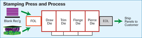
So, what are the parameters that must be defined during die construction or design that must then be validated in the stamping plant (Fig. 2), to ensure the production of parts that meet the requirements of the assembly plant?
1) Blanks typically are defined during the design phase prior to simulating formability, which determines the ability of the part to be produced without excessive thinning. Here we also define the press conditions under which the job will run, to gain historical experience. During tryout in the die shop, we verify several significant factors including material specifications (n- and r-value), blank size and shape, and the lubricant and wash characteristics. When introducing a new die in a stamping plant for tryout other significant factors come into play, such as blank location on the pallet/blank gaging, cleanliness, edge and surface condition, flatness, packaging and stacking. Defining the requirements for each of these parameters plays a significant role in optimizing process control.
Note: Defining blank requirements is the least controllable parameter, since stampers typically source blanks from a vendor, where different heats of rolled steel often are used to make the blanks. This can result in blanks with significantly different properties. Thus, stampers would be wise to source blanks from a single vendor and strive to ensure consistent n- and r-values.
2) Front-of-line parameters typically are controllable within the stamping plant. We’re talking about destacking, the presence of lubrication or washing compounds, and the material conditions noted above including surface and edge condition.
3) Die parameters of note: nitrogen pressure, draw-die gagging, draw-die bottoming and in-die lubricant-sprayer settings. The greatest variability to the process comes from the draw-die gauge setting—when not set correctly, this can allow the blank to shift and therefore affect the panel dimensions, as will running the dies off-bottom.
4) The critical parameters to control at the press are tonnage, shut height (which influences die bottoming), press speed, counterbalance setup and the NC/pneumatic cushion.
5) At the end of the press line, stamped-panel quality may be significantly affected by the condition and operation of the conveyors, lift assist, end effectors, storage racks, turntables and fork trucks. In particular, take care in designing the lift assists, conveyors and racks to ensure robustness so as to not introduce variability into the parts.
6) Last but not least, validation requires dimensional checks—until sufficient process control has been established. This includes checking parts each time a die enters the press for tryout and production. These dimensional checks—typically three stamped panels per run—become the basis for establishing process controls, and provide the ability for the stamping plant to, eventually, stop inspecting parts dimensionally.
The first step at the stamping plant is to establish that the panels represent those produced at the die shop. This includes establishing and/or replicating all of the press and die parameters discussed above, as provided by the die shop. Significant issues can arise from the part-transfer automation used; panels must be evaluated after each operation to ensure that the process of transferring the blank and panel through various die operations does not cause additional distortion. The first step: Establish the formability of the panel in the draw die in the production press, replicating results from the die-verification cell, followed by ensuring panel distortion is not occurring during transfer.
Of significance here is that the material supplied to the assembly customer, as well as review of the data during the build process in the assembly plant, may result in die changes, some of which go beyond the panels produced in the die shop. To establish process control, the stamper and die shop must fully understand this feedback and make timely adjustments to address any arising issues. Also significant: Dies typically are not surface-hardened, to allow the stamping plant to make adjustments. Therefore, care should be taken to harden die surfaces as early as possible, through chroming, nitriding, etc., to minimize die wear.
Geometric Dimensioning & Tolerancing
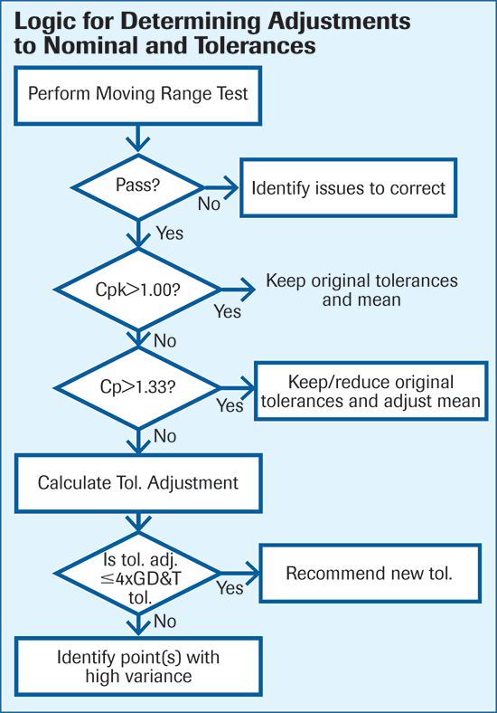
Panels produced in the stamping plant typically include GD&T, based on past experience or the expectations of the design engineer, which provides the upper and lower specification limits at interface points. This also may be based on some level of simulation to determine the requirements. This data is used to determine the true nominal dimensions of the panel (Fig. 3) and the upper and lower control limits, based on the parameters used for the process-control elements. This can be done with the use of statistical methods based on three or more runs of three parts.
Three or more runs can be defined as data collected after the dies were moved out of the press and removed from the bolster. However, care must be taken to ensure that the variation within each subgroup is not significant, along with variation between subgroups. Calculating the upper and lower control limits without running tests for the variation described above will result in significantly greater shift in nominal and/or the control limits, causing problems down the road.
You’re Happy—How About the Customer?
Once you’ve established process capability and the true means and upper and lower control limits of a stamped panel, the next step is to ensure that the customer (internal or external assembly operation) is satisfied with the newly established means and the upper and lower control limits.
Note: This should have been an ongoing process as material was submitted to the assembly line during the various builds, along with the three-part analysis. The assembly operation then decides if any of the requested tolerance adjustments cause a build issue. Any dimensional issues in an assembly or subassembly attributed to the stamping requires that the die process be improved to bring the nominal closer to the assembly requirements, along with the upper and lower control limits.
Once the die work is completed, a fresh batch of data must be submitted to ensure that the process capability is established to the requirements of the assembly plant. Once the assembly plant is satisfied with the mean shifts and the tolerance adjustments, process capabilities are deemed established; from here on out the stamping plant can monitor established process parameters for each of the steps, and run the dies confident in the established process-control process. No more part measuring.
Monitor and React
Ongoing, the stamping plant should develop a plan to collect process-control data—which can be automated in the controls—along with triggers to notify engineers should process parameters wander beyond control limits. And, develop a reaction plan should process control be lost. MF
Industry-Related Terms: Nitriding,
Nominal,
Run,
Shut Height,
Surface,
Tolerance,
Transfer,
Twist,
Edge,
Fixture,
Gauge,
Draw,
Die,
Blank,
Bottoming,
ChecksView Glossary of Metalforming Terms Technologies: Quality Control, Software


 Hari Menon