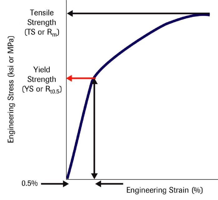
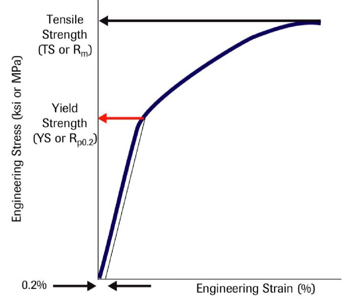
 The second technique involves drawing a vertical line at the 0.5-percent strain value and extending the line until it intersects the stress-strain curve (Fig. 2). This determines the yield strength at 0.5-percent extension under load, abbreviated as Rt0.5. These techniques result in similar but not identical YS values.
Continuous vs Discontinuous Yielding
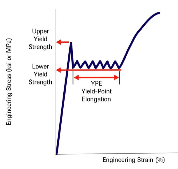
Instead of a smooth transition from elastic to plastic behavior represented by the continuous yielding curves shown in the first two figures, many steel and aluminum alloys instead exhibit discontinuous yielding (Fig. 3). Here, the stress-strain curve first reaches an upper yield point followed by a load drop to a lower yield point that extends at an approximately constant value for an amount of strain called yield-point elongation (YPE), before resuming the characteristic shape of the stress-strain curve, due to work hardening. YPE results from the formation and movement of Lüders bands, sometimes referred to as stretcher strains. Understanding the atomic interactions help explain these concepts.
Elements such as iron and aluminum have a regular and repeating crystal structure similar to a 3D arrangement of stacked ball bearings. The atoms contact their neighbors above, below and on the sides, but small gaps called interstices exist where there is no contact between the round atoms. Steel and aluminum alloys have other elements added. Depending on their relative size, these alloying elements either fit into the interstitial gaps within the iron or aluminum matrix, or substitute into the matrix and replace an iron or aluminum atom. Small elements such as carbon or nitrogen fit into the gaps in the element matrix, while larger alloying atoms such as manganese, magnesium and silicon replace an existing matrix atom. Either interstitial or substitutional alloying elements strain the atomic lattice, which is why alloys are stronger than the element upon which they are based.
 Imperfections exist in real-world crystal structures; more than a billion trillion atoms exist within a cubic centimeter of any metal alloy. These imperfections might take the form of vacancies in the structure, called dislocations. Metal motion requires that these dislocations be able to move. Under sufficient external force, atoms on one side of the dislocation jump to the other side, causing the line of missing atoms to move through the sheet. This is analogous to moving a carpet more easily by propagating a ripple from one end down its length, rather than just tugging from the opposite edge.
The alloying elements that strain the lattice migrate by diffusion to the dislocation vacancy sites, as these areas have more room to accommodate the alloying elements. With the alloying element now occupying, or pinning, the dislocation, atoms need greater force to move from one side of the dislocation to the other. Visualized on the stress-strain curve, load increases with little corresponding deformation. After atoms traverse the gap, the metal continues to move at the lower force requirement, meaning that deformation increases with little corresponding increases in load. This occurs until encountering another pinned dislocation, again needing a higher force to overcome it.
Returning to the carpet example, the pinned dislocations act like carpet tacks. Propagating the ripple requires higher force to pop out the tack, but once it is out, the ripple moves freely and easily until encountering the next set of tacks.
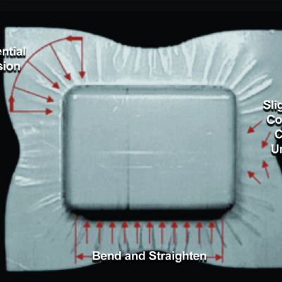
The repeated locking and unlocking of dislocations by the alloying atoms creates a visually apparent surface distortion called Lüders lines, which continue at approximately a constant stress until the entire sample has yielded. The total strain affected by this type of deformation is the YPE. In addition to being visually undesirable, fluting during bending is one example of the negative effects on panel quality associated with YPE.
Temper rolling, or similar operations at the steel mill, suppresses YPE by creating additional dislocation sites free of migrated alloying elements. Greater reductions are more effective, but steel mills balance this benefit against the associated work hardening and decreased ductility caused by the rolling.
Steelmakers produce formable deep drawing steels free of aging by using an ultralow carbon chemistry—typically less than 0.003-percent C—achievable with vacuum degassing. Also critical are low-nitrogen practices. Using titanium, niobium or vanadium to tie up any remaining carbon and nitrogen in solution produces a stabilized vacuum-degassed interstitial-free steel, eliminating the possibility of YPE and Lüders lines. MF
Industry-Related Terms: Alloys,
Bending,
Blank,
Drawing,
Ductility,
Fluting,
Form,
Lines,
Plastic Deformation,
Punch Direction,
Surface,
Work HardeningView Glossary of Metalforming Terms
See also: Engineering Quality Solutions, Inc., 4M Partners, LLC
Technologies: Materials


 Strong interatomic bonds hold atoms together. When a punch first contacts a sheet metal blank, the applied forces are low enough that the blank returns to its flat shape when punch direction reverses. At the atomic level, the force applied by the punch stretches the bonds without breaking them. The lack of broken bonds means that the atoms can return to their neutral position after removal of the force. During this elastic deformation, there is a linear relationship between the applied stress and the metal deformation, measured as strain. The slope in this region of a stress-strain curve is the elastic modulus.