Coilers, Payoffs
August 1, 2012Comments
...and the proper methods of installing and maintaining them.
Most stamping and forming operations begin with coiled material that must be fed into either a shear or stamping press. The decoiler, payoff reel, recoiler, tensioner and other coil-handling equipment require constant maintenance.
When one looks at coiling and payoff equipment in the metalforming field, there is little mention of the care and methods of proper maintenance. Often the maintenance department is focused on keeping the stamping presses or shears running, while throwing the coiler/payoff machinery “under the bus.”
Mandrel Installation a Critical Success Factor
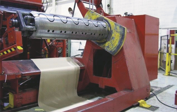 |
| To ensure proper coil gripping, segments should be straight, free of damage and, when a dial indicator is placed on any part of the OD, should not exhibit excessive runout. Out-of-flat segments that exceed 0.015 in. of bend from end to end should be repaired or replaced. Also check segments with an indicator to look for loose fit. If clearance exceeds 0.020 in., immediately repair or replace the segment. |
Originally, coil stock was fed into a machine based on crude shafting supported by bearings. Now, precision bearings hold expanding leafs that grip the inner diameter of the coil. Each leaf is precision machined and centered onto the shaft via some form of expansion device, also precisely machined. This allows for concentric running of the coil to the shafting that supports it, as well as smooth operation and alignment with little or no delay to the metalforming process.
The nature of the installation determines how productive a mandrel will be, as well as the longevity of not only the mandrels but also of the coil payoff and uptake equipment. Several factors must be addressed during installation to ensure that the setup provides the required stability and alignment accuracy.
Although lighter units are self-contained and do not require separate foundations, a mandrel often is subjected to high vibrations during use. Grommets are used to floor-mount and level smaller cradles and reels. When a separate foundation is not planned, the metalformer should consider use of isolation mounts. A carefully planned and engineered foundation should be sought out when installing mandrels handling 10,000 lb. or more. Whenever possible, consult the OEM for installation assistance and recommendations.
On the Level
The leveling process must be exact and repeatable in order to avoid damage to the material and equipment. Installation of the mandrel is as precise an operation as the setting of the press. As such, take care to ensure that the mandrel is set in three-dimensional alignment with the press and with the center of gravity. This will help prevent damage to the mandrel and the die.
In the past, mandrels were aligned using makeshift centerlines and bubble levels. This method often caused errors in the final feed, resulting in maintenance failures. Current leveling methods include laser alignment of the equipment, whereby the centerlines of the mandrel are held within thousandths of an inch in relation to the centerline of the press or shear. The use of laser-alignment instrumentation is the key to ensuring that the mandrel is properly set up prior to its running. Concerns with product quality, tooling wear, maintenance and safety all are minimized or eliminated when proper alignment is established.
During installation, it is critical that metalformers properly guard the mandrel and other coil-related equipment. OEM guards and any other auxiliary guarding should be fastened securely in place. Also be sure to eliminate pinch points and points of employee contact. Enforce OSHA standards to avoid injuries. In some installations, the addition of safety light curtains and photoelectric sensors find use for guarding a mandrel and coil-related equipment, in addition to standard hard-guarding options.
Mandrel Upkeep and Maintenance
Mandrels are constantly subjected to coil-related damage. Their constant use in metalforming operations places tremendous loads on the mandrel, causing wear and damage to mandrel components. The combination of improper operation and normal wear and tear on a mandrel can create maintenance headaches. Preventive maintenance and inspection should take place in several areas:
• Coiler frame—Frames require careful inspection. They should be fabricated rather than held together with fasteners, because under normal load conditions mandrels endure so much vibration that fasteners can fail, causing the frame to become unstable. Any frame that does include fasteners should be checked regularly to ensure all fasteners are properly torqued. Additionally, metalformers should inspect frames every six months for squareness, alignment and bearing bore dimensions. All welds and other structures should be nondestructively inspected at least every two years using dye-penetrant testing to look for cracks caused by overuse or misalignment. Check all wear points and make required repairs immediately.
• Gearbox (if applicable)—Gearboxes are a constant source of wear. Check gear tooth profiles and backlash with a feeler gauge to monitor tooth wear. Excessive backlash will result in damage and destruction of the gearing. Every two years, employ a qualified bearing engineer to remove and inspect all bearings. Also check bores for dimensions and alignment, and contract with a qualified machine and fabrication shop for damage repair.
• Mandrel leafs or segments (overleafs)—To ensure proper coil gripping, segments should be straight, free of damage and, when a dial indicator is placed on any part of the OD, should not exhibit excessive runout. Out-of-flat segments that exceed 0.015 in. of bend from end to end should be repaired or replaced. Also check segments with an indicator to look for loose fit. If clearance exceeds 0.020 in., immediately repair or replace the segment. Take a total indicator reading (TIR) with the segments in place and a dial indicator placed on a segment and the mandrel turned 360 deg. A TIR in excess of 0.010 in. indicates that damage has occurred and repairs should be made.
• Mandrel shaft and bearings—These components are the heart of the coil-feed operation. Shafting should have the same TIR as the mandrel segments. Use dye-penetrant inspection to uncover cracks and trigger repair or replace procedures. Inspect the bearings on the mandrel shaft at least every two years. Hire a qualified bearing inspector to determine if bearing life has been exceeded.
• Mandrel brake—The brake system is critical to any coiler mandrel, and should not require constant repair or relining. Inspect brake linings weekly, and replace the lining when it falls below the minimum OEM-specified thickness. Should the braking system fail to perform or require constant relining, consider use of a hydraulic brake system. If your system requires attention more than every six months, it’s time for an upgrade.
• Lubrication system—A well-functioning lubrication system ensures that bearings, slide surfaces, shafting and other moving components will last a lifetime. Each point of lubrication must be checked for proper operation. Disconnect the lubrication line and engage the pump. Then check for the required amount of lubricant, and its cleanliness. Any point in the system that lacks clean and adequate lubricant should trigger maintenance procedures. Note: Metalformers employing manually operated lubrication systems should consider upgrading to an automated pneumatically or electrically run system.
• Actuation devices—Inspect these devices, which actuate mandrel-segment expansion and contraction, every six months. These devices include but are not limited to cylinders, wedges, slides and pull rods. Check each component for cracks, wear, distortion and other signs of deterioration. A thorough inspection will reveal troubles long before a breakdown occurs.
• Motors and other electrical apparatus—Although some coil systems do not have electric motors, most do and these systems should be checked weekly to ensure proper functioning. Every five years, metalformers should remove and inspect motors, and clean, bake and dip as needed. MFView Glossary of Metalforming Terms
See also: United Machine Corporation
Technologies: Coil and Sheet Handling