Peter Ulintz Peter Ulintz
Technical Director

Four-Slide Tooling

April 23, 2019
0
Comments


Most of the topics addressed in this column during the past 13 years cover metal stamping processes and dies. However, metal forming includes more than just stamping. Therefore, last month we addressed slide-forming processes. This month’s topic: four-slide tooling. And in coming months we’ll cover more metal forming processes and associated tooling challenges.

Stay tuned.

Essential Elements


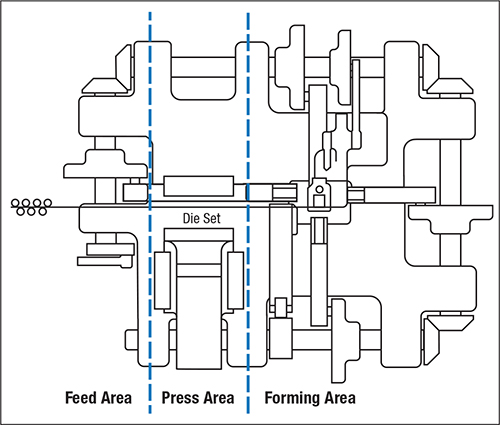
Fig. 1—Main elements (areas) of a four-slide machine.
Four-slide process planning and tool design must consider three major machine elements (Fig. 1): feed, press and forming area. Each time the machine cycles, a feeding mechanism moves metal strip a specified feed length—the blank length plus the carrier tab. The feed motion usually consumes 180 deg. of the 360-deg. machine cycle to move material one feed length. Some four-slides have 90 and 180-deg. feeds. When part complexity requires that the maximum 270 deg. be available for the forming motions, this calls for a 90-deg. feed.

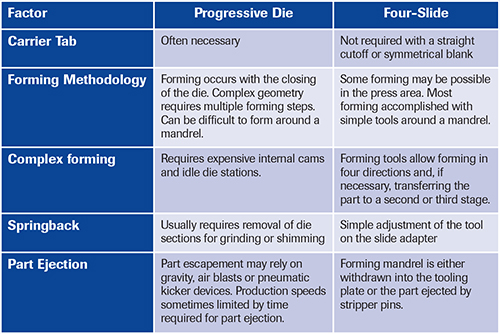
Carrier-tab lengths vary by part design, material thickness and/or processing method but should not be less than three times the strip thickness. Blanks separated by a straight cutoff or that have matching shapes at each end, as well as most wire forms, do not require a carrier tab.

The press area at the center of the machine enables punching and sometimes light forming of a strip in one or more die stations. The distribution of punching loads among the die sets should balance as much as possible. Positioning high-tonnage operations like gutting and coining in the center of the die sets is a prime objective.


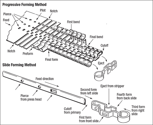
Fig. 2—When compared to progressive die-stamping for the same part design, the four-slide process exhibits simplicity of tooling while providing an economic advantage. Source: PMA Design Guidelines, 4th Edition.
The forming area of a four-slide machine also contains a cutoff slide. Cutoff occurs where the part changes from a section of the strip (or wire) to an individual blank. The location of the die set(s) in the press area must be precise in relation to the cutoff station. For symmetrically formed parts, set the distance between the cutoff and the forming mandrel centerline at one-half the feed length. Nonsymmetrical forming requires an engineer or setup person to determine the amount of forming required on each side of the forming mandrel before setting the cutoff position accordingly. After securing cutoff, mount the die(s) at an exact multiple of the feed length from the cutoff to the press area.

A cam-operated stock clamp advances through the front tool to hold the bank material against the forming mandrel throughout the forming cycle. Timing the stock clamp to hold the blank against the mandrel a few degrees of machine rotation before cutting occurs provides optimum control of the blank through the forming process. Depending on design, the part may be formed on the same plane as the feed line, or partially formed on the feed plane and then moved to a lower position on the forming mandrel, where additional forming steps occur during the next cycle.

Advantages Over Progressive Dies

Depending on part size and complexity, four-slide and multi-slide machines can produce parts more economically than progressive dies because the forming operations occur outside the die area, utilizing motions built into the machine. In contrast, progressive dies require several internal cams to transfer the vertical ram motion of the press into the required horizontal forming motion inside the die. Internal cams add significant cost and complexity to the die.


Fig. 3—Process parameters and the corresponding advantages of four-slide processes.
Fig. 2 depicts the relative simplicity of tooling and the economic advantage of a four-slide process compared to using a progressive stamping die for the same part design. The progressive die requires 20 stations to produce the completed part, half of them allocated to multiple forming steps. A notching step in station number four is required to establish the finished part width and create a part carrier in the strip.

In contrast, the four-slide process uses a coil width that matches the finished part width. A die mounted in the press area punches three holes in the strip in one press cycle and the strip advances a prescribed distance to the forming area where it is concurrently cut off, formed and ejected.

Fig. 3 identifies additional process parameters and the corresponding advantages of four-slide processes. Clearly, four-slide processes have at least three significant advantages over progressive dies:

  • Forming occurs outside the die, with actions independent of the press station. In a progressive die the forming actions are directly linked together and all must occur inside the die.
  • Tool motions in a four-slide machine are independent of timing and direction from each other. This allows for adjustments to stroke, shape and timing of each tool to compensate for dimensional variation, tool wear or changes in material properties and thickness.
  • Tool adjustment and maintenance are easier, due to greater accessibility and visibility of the tools in the forming and press areas. MF
Industry-Related Terms: Blank, Center, Coining, Die, Mandrel, Notching, Ram, Stroke, Thickness, Transfer, Forming
View Glossary of Metalforming Terms

Technologies: Other Processes

Comments

Must be logged in to post a comment.
There are no comments posted.

Subscribe to the Newsletter

Start receiving newsletters.