Stretching and drawing operations require proper location of processing lubricant on the sheetmetal blank. Stretching operations require lubrication between the sheetmetal and the punch face to provide a low friction site for the material to slide and stretch. The material on the die surface should not be lubricated, creating sufficient friction to inhibit material from drawing-in from the flange.
In deep-drawing operations, do not lubricate the sheetmetal surface under the punch, to promote friction between the punch face and workpiece. The die surface and die entry radius must be lubricated to ease material flow.
Too often, press shops overlook these important lubrication conditions and apply lubricant to the entire sheet before it enters the die, with no consideration for the forming mode. Changes in lubricant quantity in critical zones on a stamping can alternate the forming mode between drawing and stretching, which can complicate problem solving and contribute to inconsistent part quality.
Pesky Wrinkles and Fractures
Pressure pads serve different purposes for stretching and drawing operations. During stretching, lock beads prevent material movement across the pad. Because such movement from the flange is restricted, material contacting the punch stretches.
During deep drawing, restraining forces are significantly lower to permit some material flow across the blankholder (a type of pressure pad), yet high enough to prevent wrinkle formation. The blankholder surface contacting the sheetmetal is usually smooth, and sometimes polished, to ease material flow. When deep drawing irregularly shaped parts, certain areas of the binder may be roughened to help balance material flow.
When wrinkles do occur, their locations on the part can help differentiate between stretching and drawing modes. Wrinkles on or around the punch nose—sometimes called puckers —could indicate insufficient restraining forces. Pressure may need to increase to as much as 10 times the punch force, depending on material type and thickness. To promote stretching, stampers can increase the blank size, reduce lubrication between the sheet and the pressure pad, roughen the pad or add lock beads.
Wrinkles in the flange area or near the die radius indicate the presence of in-plane compressive forces synonymous with deep drawing. Blankholder pressure may need to increase to as much as 40 percent of punch force, depending on material type and thickness. Reducing the size of the die entry radius (< 10t), adding draw beads or reducing punch-to-die clearance also may help.
Punch-to-die clearances in stretching operations generally are equal to material thickness (1t). In drawing operations, compressive forces in the flange cause the material to thicken, requiring additional clearance of 10 to 25 percent or more, depending on material type.
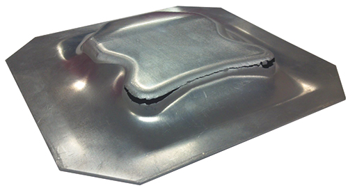
When fracturing of the sheetmetal occurs, the slide position will differ depending on the forming mode. Drawing failures generally occur within the first third of the draw depth (see image). Forming loads and friction are greatest early in the stroke and diminish in magnitude as the blank area diminishes. Conversely, stretching failures generally occur near the end of the forming stroke due to excessive thinning and work hardening.
Venting
Most tool and die professionals understand the need to vent draw dies. Venting allows trapped air and lubricants to escape and prevents vacuum problems (part sticking) on the upstroke.
However, venting also is important for stretching operations to prevent trapped air and fluids from causing bursting or fracturing in highly stretched areas. Unfortunately, after breakage occurs the fluid and air are released, taking with them any evidence of the root cause of the failure. The stamper likely will waste time and effort on tool modifications and material-specification changes, when the real culprit was trapped air and fluid. MF Technologies: Lubrication, Tooling


 Changing a tooling parameter that promotes material stretching will not solve a drawing-related problem; good examples include punch and die radii. In stretching operations, punch radius is critical. It must be very smooth and large enough to promote material stretching across the face. Then, opt for a relatively small die radius to restrict material flow over the die surface. In addition, establish a rough pressure-pad surface to inhibit material flow and force the material in contact with the punch.