Peter Ulintz Peter Ulintz
Technical Director

A Close Shave

July 1, 2010
1
Comments


Question: I have a low-carbon steel part that is relatively thick—at least it is for us—at 0.125 in. It also has two holes and two tabs with tight tolerances (±0.001 in.). We would like to produce this part in a progressive die using shave operations rather than having it fineblanked. Unfortunately, shaving in a stamping die is something we have little experience with; could you provide us with some guidelines?

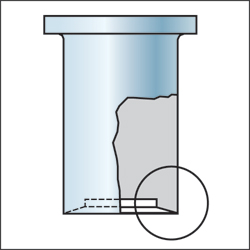
Answer: A simplified version of your stamping is shown in Fig. 1. The red areas depict those features that you wish to have shaved: two round holes and four straight edges. 

Shave operations generally are associated with punched openings such as holes, but many free-edge features also can be shaved. In fact, most stamping applications requiring close tolerances on die-cut edges can be good candidates for shaving.

Here are some general guidelines for processing shaved features: First, let’s consider the 0.375-in.-dia. holes in Fig. 1. To achieve these diameters from a shave punch it will be necessary to punch the holes somewhat smaller than 0.375 in.; but how much smaller do we make them?

Close Shave Fig.1
 Fig. 1
Typically, the amount of material to be removed by shaving is about 10 percent of material thickness, for most materials. This provides a good surface finish and leaves enough material in the “scrap ring” for slug retention. This is an important point, because slug retention is generally considered to be the most common problem associated with shaving operations. 
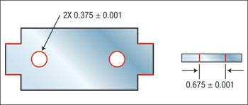
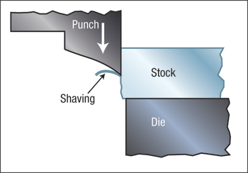
Why is slug retention such a problem? Here is my theory: Since the amount of material to be removed by shaving is somewhat related to the size of the fracture zone (die break), many die makers and tool engineers mistakenly believe that reducing the size of the fracture zone—by reducing the punch-to-die clearance in the punching station—reduces the amount of material being shaved. Thus, reducing shaving-related problems. Actually, this approach causes more problems than it solves.

Reducing punch-to-die cutting clearance will produce a larger shear (cut) band, a correspondingly smaller fracture zone and generate small burrs on the backside of the punched holes. A larger shear band creates a larger cold-worked zone, which makes shaving more difficult due to the increase in cutting forces, friction, punch fatigue, chipping and punch wear. The burr resulting from the tight clearances interferes with accurate part positioning over the matrix opening and it is very difficult to remove by shaving alone. A smaller scrap-ring web also results, making it very difficult to shed the scrap and keep it out of the die.

The proper punch-to-die clearance, according to Dayton Progress research, is the largest clearance that does not produce a burr. This can be as much as 10 to 20 percent per side, depending on the material thickness and type. These “engineered” cutting clearances optimize tool life and minimize work hardening inside the hole. 

A close shave hollow ground concept
 Fig. 2—Hollow-Ground Concept

Proper shave clearance, on the other hand, will be very tight, usually 1 to 1.5 percent per side. Too much clearance results in a shear and “rebreaking” of the hole. In the example part, the proper shave punch appears to be 0.375-in. dia. However, when specifying shave punch diameters, remember that the resulting hole size will be slightly smaller than the actual punch size, usually by 0.0002 to 0.0004 in., due to elastic recovery after shaving. This means the shave punch in our example part should be ordered at 0.3753 in. dia. The corresponding die matrix should be 2 to 3 percent larger and have a ¼ in. land before transitioning into ½-deg. taper. 

For very close tolerances, or when shaving very thick materials with pronounced die-break or taper, more than one shaving operation may be needed. When two shave steps are employed, the amount of material shaved in the second step should be one-half that of the first step. So if a total of 0.009 in. of material is to be shaved, 0.006 in. should be removed by the first shave punch and 0.003 in. removed by the second.

Since shaving is more of a machining operation (cutting) than a stamping operation (punching), a rake angle machined on the shave-punch face usually is necessary. This would be similar to the rake angle found on a cutting tool.

A close shave-fig. 3 close up view
 Fig. 3—Close-Up View

The “hollow-ground” shave punch concept is shown in Fig. 2 (courtesy of David Smith and Associates) and provides a cutting-tool action. This modification can improve surface-finish quality and extend punch life. Fig. 3 provides a close-up view of the concept. 

Establishing the proper back-rake angle for each application is somewhat of a black art that requires trial-and-error development. Some brass and bronze alloys do not require any back angle at all; mild steels, depending on hardness, may require 20 to 30 deg.; some aluminum alloys may need as much as 45 deg.

Due to the close cutting clearances and high cutting forces associated with shaving operations, a guided stripper plate may be required to adequately support the punches and to maintain accurate punch-to-die alignment. This can greatly reduce punch chipping (a common problem) and premature wear or shearing.

When shaving a free-edge (i.e. trim line edges), the same rules for punched holes also apply. In addition, the free-edge shave punch must be heeled and properly supported to prevent deflection due to unbalanced cutting forces.

Finally, a good lubricant should be chosen whenever shaving is performed. Depending on the type of material and its thickness, a heavy-duty EP lubricant used for fine blanking, broaching or in-die tapping operations may be necessary. Work closely with your lubricant supplier for optimum results. MF

Industry-Related Terms: Surface, Tapping, Thickness, Work Hardening, Alloys, Blanking, Brass, Burr, Die, Plate, Point, Scrap, Slug, Stripper
View Glossary of Metalforming Terms

Technologies: Tooling

Comments

Must be logged in to post a comment.

Kevin C. THU, JUN 11, 2020 @ 1:39 PM

I have some similar questions to this initial request. We are making a three stage shave die for some .157 thick aluminum. Any pointers you could offer outside of what was presented in your reply? thanks!


Subscribe to the Newsletter

Start receiving newsletters.