Examining the Secrets of Shaping Sheetmetal
June 1, 2017Comments
Few people understand well the process used to fabricate two-piece (body and tear-top) beverage cans. For example, the two-piece can may begin as a blank of Type DR-9 steel that has been cold-rolled, annealed, and then again cold-rolled 35 percent and used without further annealing–producing sheets with full-hard status.
The rollforming process, used to initially harden the workpiece material, comprises a series of bending operations that start at the center of the blank and work outward. This allows early forming of the edge material to lock the sheetmetal, creating a stretch contribution. One benefit: The designed blank width is the sum of the neutral-axis widths. Therefore, the amount of material needed to form a complex design can be computed early in the deformation process.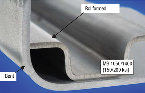
Fig. 1—Rollforming and bending of martensitic steel can have unexpected results. AHSS Application Guidelines—Ver. 4.1.
To illustrate this, we rollformed sheets of martensitic steel (MS 1050/1400) to their smallest radius (Fig. 1). The same MS steel also was bent to its smallest radius; rollforming generated the smallest radius.
Forming the Can Body
Transforming the rollformed hard-steel blank into a usable can body then requires a five-stage process (Fig. 2).
Stage 1—Draw: The flat blank is converted to a circular cup (shown at the left of the arrow in Fig. 2). This creates a starting point that can be reworked into many configurations.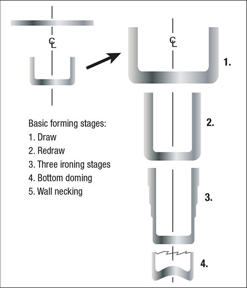
Fig. 2—Hardened steel blanks undergo a five-stage process to form a usable can body.
Stage 2—Redraw: At stage 1 the cup has a dimension that is too wide and too short. A redraw operation forces a correct diameter by using a punch and die of smaller diameter.
Stage 3—Wall ironing: To utilize the excess thickness of the can body, a die is constructed to thin the walls of the can in a process that will cause an increase in can height. The example in Fig.2 has a die with three different thicknesses. As the punch drives the cup through the die, the cup wall becomes thinner and longer. This process allows the metalformer to adjust wall thickness and cup height as needed.
Stage 4—Bottom doming: Not all deep-drawn cups have flat bottoms. Some have hemispherical or otherwise configured bottoms—pushed inward or outward, for example. The forming process then turns from a material-independent cup-draw operation into a complex operation where the hemisphere is stretch-formed—highly dependent on material properties. The interaction between the drawn cup and hemisphere is not additive but interactive; add a stretch-form area to a simple cup draw and you create additional problems.