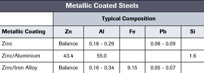
The coatings under consideration (see the accompanying table):
- Zinc—Referred to as hot-dipped galvanized (HDG), this coating has the appearance of a fine spangle that results when the coating solidifies.
- Zinc-aluminum—or an aluminized coating (Al-45Zn).
- Zinc-iron—Referred to as galvanneal, this coating has a smooth, dull, matte-gray finish.
 No other coatings will be discussed here due to the vast array of coating combinations available.
RSW Parameter Primer
Successful RSW results from using the correct process parameters:
- Force between the electrodes
- Current at the electrodes
- The length of time that the current flows through the electrodes
- Electrode temperature
- Electrode-face diameter (the contact surface, which must be held constant).
The electrode force holds the workpiece materials together and creates a specific amount of resistance. Then, a specified amount of weld current passes through that resistance for a set amount of time to create enough heat in the material’s faying surface (the area between the workpieces) to create fusion. Finally, force forges the parts together.
We recommend the use of internally water-cooled copper welding electrodes to keep them at a workable temperature—as copper heats, its resistance increases. Also, water cooling will reduce heat buildup at the contact area of the electrode and work—the second-highest resistance value of the welding circuit.
 The amount of total heat generated by the contact resistance at the interfaces and the bulk resistance in the workpiece is governed by Joule’s Law, H = I2RT.
H = total heat; I = weld current; R = total circuit resistance; T = weld time
Thus, weld quality directly depends on localized heat generation, influenced by the contact face of the electrodes. This determines the weld’s current density (A/in.2). Note that degradation (mushrooming) of the electrode tip-face diameter will reduce the electrode’s ability to:
- Provide the necessary weld force
- Set the weld current density
- Cool the interface between the electrode face and workpiece material at the end of the weld.
Why the Coating Affects Weld Quality
The control functions of an RSW machine may be used to melt and move the coating away from the weld zone prior to welding. For example, a slightly higher weld force can squeeze out the molten coating. Here, a higher welding current may be required to compensate for the reduction in resistance caused by the higher weld force. We recommend use of the higher weld force due to the narrow range between the melting and boiling points of zinc-based coatings, and to reduce the tendency of the zinc to vaporize.
If we choose to not move the zinc coating away from the weld area, we must look at what happens to the copper electrode, and decide how to deal with the coating and how it affects the contact resistance. The coating alters weldability in two ways. First, the low melting point of the coating alters the contact resistance. For example, welding coated steel requires significantly higher welding current than for uncoated steel, due to the reduced contact resistance from the zinc layer.
When welding coated steel, the zinc layer at the electrode/sheet interface melts first (due to zinc’s low melting point) and most of the molten zinc squeezes out during the first few welding-current cycles. Even though a significant portion of the zinc squeezes out of the compressed area under the electrode face, a considerable amount of zinc will remain trapped at the sheet-to-sheet interface; this also contributes to the reduction of the overall resistance.
 Galvannealed steel sheets have a Fe-Zn surface coating, which has substantially higher bulk resistivity than free zinc. Therefore, the influence of the galvanneal coating on contact resistance is less.
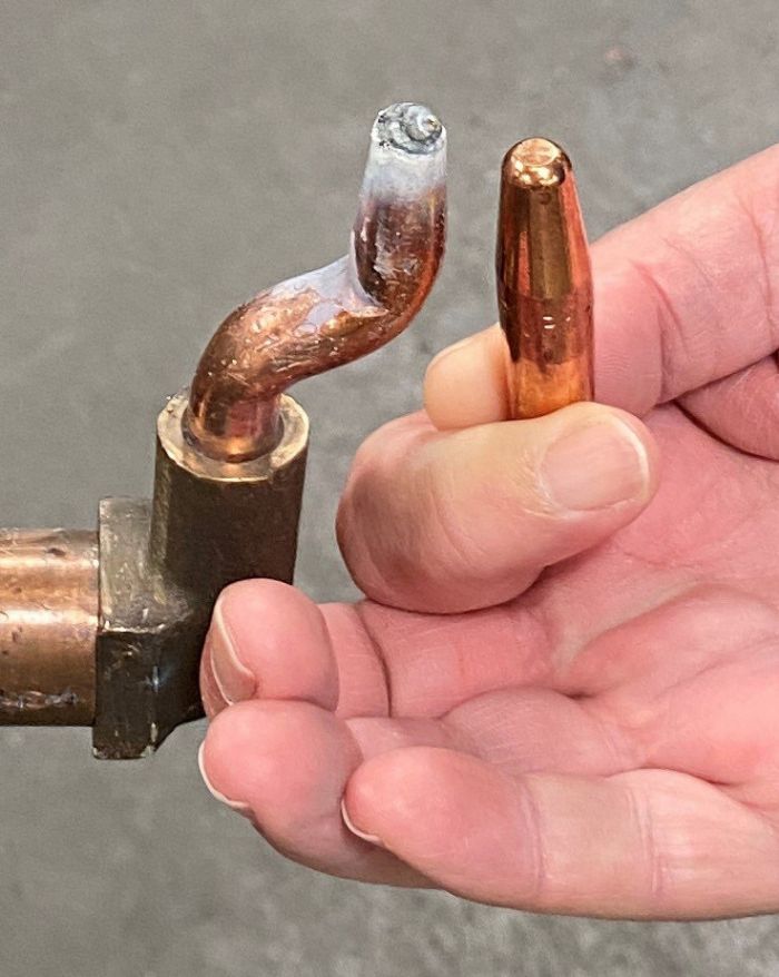
Secondly, interactions occur during the welding process between the electrodes and the coating. The high temperatures and forces that develop during welding provide the driving force for these interactions, and the coating (mostly zinc) will alloy with the copper electrodes. The resulting brass alloy then acts as the electrode-face material and mushrooming (tip-face degradation) causes an increase in the contact area.
This increase in contact area decreases the current density and dramatically reduces weld strength. These two effects combine to rapidly accelerate the wear rate of the electrodes—usable tip life may be as short as 250 welds before requiring dressing, depending on the composition and geometry of the electrode, compared to electrodes used for welding uncoated steels that may endure thousands of welds between tip dressings.
Eventually, unless we make the proper adjustments to weld current and weld time or mechanically dress the electrodes back to their original tip-face diameter and condition, the resulting weld nuggets will fail. The degradation process begins with alloying of the electrode-tip face with the metallic coating, primarily around the edge of the electrode tip. As welding continues, the alloy layers grow until the electrode begins to stick to the work. Retraction of the electrode tip strips the alloy layers away and accelerates further erosion and pitting.
Electrode impact, high-temperature deformation, electrode-face erosion and alloy buildup on the edge of the tip combine to increase the electrode’s tip diameter. This gradual increase in contact area causes a corresponding decrease in current density, which results in welds with decreased nugget size and strength.
Well-Dressed Tips
Proper tip dressing will pay huge dividends when welding coated steels. Establish a routine of dressing tips on a regular schedule and do it well before weld failures occur. Tip-dressing tools vary from a radiused hand file (not the optimum method) to a motorized dresser equipped with cutter blades selected to match the electrode’s desired weld face. Fabricators can dress the tips while they’re still installed on the RSW machine or remove the tips and dress them in a drill press or lathe.
After dressing the tips, or installing new ones, make a few welds on a scrap piece of the same material as the workpiece, to season the tip faces. Then use a Scotch Brite pad to buff the weld faces, leaving a stable coating of zinc. At this point, it’s best to leave the zinc on the tip faces alone and only remove the mushroomed portion during subsequent dressings.
Note: The brass-like appearance of the weld nuggets is good. If the weld face starts to stick, immediately redress or replace the tips and season them again.
RSW Machine-Control Functions
Most rust-preventive metallic coatings melt at 700-800 F, while most steels melt at around 2700 F. Several RSW-machine-control functions will bring the coating to its melting point prior to weld formation so that the coating will squeeze out of the weld area during the early stages of the weld sequence. These functions include:
- Upslope: A programmed gradual increase in weld heat prior to applying full welding current. Generally, the user programs the number of weld cycles dedicated to the upslope mode and at what amperage the upslope starts. Upslope, the traditional method of controlling weld heat when welding coated steels, may not be as effective as other more modern techniques, described below.
- Preheat/cool/weld: This sequence starts with an initial pulse of lower heat to liquify the coating, followed by cooling time (a period of no heat) that allows the coating to squeeze out from under the electrode to the outer edge. Then a final weld sequence forms the nugget. This technique works best for sheet metal to 12 gauge.
- Pulsation: This sequence, typically used for sheet metal 11 gauge and thicker, employs a series of heat/cool impulses to move the coating out of the way to achieve deep, solid weld nuggets. A common procedure uses five weld/cool impulses, with the total weld time for each impulse approximately 25 percent of the weld time used for welding uncoated steel.
- Heat stepper: This control function automatically increases the welding current over time, until the electrodes require dressing, to compensate for the unavoidable growth of the electrode face. It also keeps welding current density as constant as possible. A properly programmed heat-stepper function can dramatically increase the number of good welds made between dressings.
Proper Electrode Cooling, Shape and Composition
Studies have shown that keeping the cooling-water temperature below 65 F and at a flow rate of 0.5 gal./min. or more, along with a good heat-stepper program, can increase electrode life from less than 500 welds to 3000 welds or more between dressings. But the lower water temperature may cause condensation to occur within the transformer, which should be avoided, so one must balance the condensation issue with the cooler temperatures to prolong electrode life. Regarding electrode-tip geometry, other studies find that a truncated-cone nose profile with an included angle between 90 and 140 deg. will optimize welding of metallic coated steels.
Regular removal of any buildup on the electrode tips will maintain a high current density, usually resulting in a large weld nugget. The ratio of current density at the electrode shoulder (or edge face) to current density at the face center will decrease with increasing included angle.
Metal formers can select from several electrode alloys for RSW of coated steels:
- Glidcop (trade name)—a Class 20 copper electrode alloyed with aluminum oxide that has been dispersion-strengthened. Its characteristics of resisting heat and sticking prove favorable when welding coated steels.
- Z-trode (trade name)—a Class 2 copper-chromium electrode with high electrical conductivity and thermal conductivity, along with maintaining high-strength characteristics.
- TiC MMC (trade name)–titanium-carbide coated copper electrodes—a strong, hard ceramic material with good electrical and thermal conductivity, combined with high hardness and strength.
Conclusion
Reduced weldability and tip life when welding metallic coated steel may occur due to the severe welding parameters required to form a weld nugget, along with the formation of zinc-copper alloy on the electrode’s weld face. New electrode-material developments designed to minimize this problem may not suit every application nor be cost-effective.
Using the control features described above, to move the zinc from the weld area, allows welding with just minor adjustments as compared to welding uncoated steels. Modern weld controls allow precise weld-heat manipulation during weld-nugget formation. It may come down to something as simple as reconsidering the weld schedule and how often the electrode tips are dressed. MF
The author thanks Roger Hirsch of Unitrol Electronics and Josh Garmon and Tom Snow of T. J. Snow Company for their contributions to this article.
Industry-Related Terms: Alloys,
Aluminum Oxide,
Brass,
Center,
Conductivity,
Edge,
Electrodes,
Form,
Gauge,
Layer,
Nugget,
Scrap,
Strips,
Surface,
Thickness,
WeldabilityView Glossary of Metalforming Terms
See also: T. J. Snow Company
Technologies: Welding and Joining


 Presented are different perspectives: