Continuous Seam Welding
During continuous seam welding, the wheels continue rolling as the welds form. Unlike the intermittent process, continuous seam welding imposes the constraint of a fixed time window to make each weld. Since there is no opportunity to vary the weld time for each nugget, all adaptive decisions and compensating actions must occur as each weld forms.
The continuous process allows production at much higher speeds than can be achieved with intermittent seam welding. However, ensuring a repeatable process, when using a conventional control, requires good control of velocity. Excess wheel velocity will cause cold welds; insufficient wheel velocity will produce hot welds.
Fabricators select from three modes of continuous RSEW:
1. Welds produced using the same wheel velocity—The wheels clamp the parts and start rolling. Welding does not commence until after the wheels accelerate to the programmed welding velocity, and the wheels do not decelerate back to zero until the last weld in the seam has been completed.
This is the easiest arrangement for fabricators to manage with conventional welding equipment. As long as consistent parts are presented to the welding machine with consistent tooling, and the process maintains consistent control of electrode force, wheel velocity, heat and time, then managing the shunting phenomenon during the first few welds in the seam generally becomes the only remaining process-specific condition to address.
|
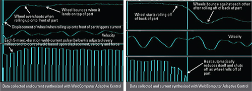
| Fig. 3—An adaptive RSEW control automatically adjusts weld-heat input in relation to the position of the electrode wheels. This is shown on the left, the front edge of the part, and on the right, the back edge of the part. |
2. Welds produced with varying wheel velocity—The wheels clamp the part and begin rolling, and welding commences before the wheels finish accelerating to the programmed welding velocity. Welding at the end of the seam continues, even as the wheels decelerate toward zero.
This arrangement requires special actions at the beginning and end of the seam to avoid forming excessively hot welds at the lower velocities. One such action: Employ upslope heat at the start of the seam and downslope heat at the end of the seam. Achieving consistent welding performance requires precise scaling and coordination of the heat upslope with the rising wheel velocity at the beginning of the seam, and precise scaling and coordination of the heat downslope with falling velocity at the end of the seam. This coordination can be difficult to achieve in practice. Also, as wheel speed increases, instantaneous velocity fluctuations increase from factors such as variable loading of the part presented to the machine, gear backlash, belt stretching and vibration, and machine mechanical resonances. These variations can lead to inconsistent weld-nugget size.
3. Welding occurs edge-to-edge across the entire part—Fabricators use edge-to-edge seam welding to manufacture products such as water heaters, 55-gal. drums, pails and aerosol cans. As each weldment feeds through the RSEW machine, the wheels must roll up onto the front edge of the part, travel along its entire length, and roll off of the back edge.
Most manufacturers of these types of parts attempt to control the process by employing upslope heat at the start of the seam and downslope heat at the end. A limit switch or proximity sensor detects the part approaching the seam wheels and triggers the start of the weld-schedule sequence. A sensor that detects the approach of the back end of the part triggers the downslope at the end of the seam.
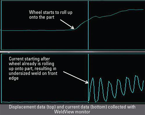
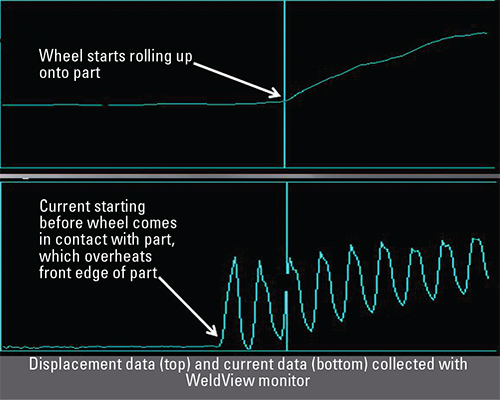
Often, this process produces high scrap rates from inconsistent weld performance, and as production speed increases so do welding inconsistency and scrap rate. Typically, welds on the front edge of the part are either too cold (because welding heat started after the wheels already started to roll up onto the part), or too hot (because welding heat started before the wheels began to roll up onto the part). Regardless of how the fabricator may adjust the proximity sensors, the time uncertainty of the part front-end detection system, coupled with variability in the time from when the detection takes place until the part contacts the seam wheels, makes it nearly impossible to accurately synchronize the start of heat with the front edge of the part entering the wheels.
Synchronizing the downslope on the back end of the part, and turning off the heat at the right time, creates similar problems. If the heat shuts off before the wheels begin to roll off of the back edge, the welds will be too cold, and if the heat stays on too long, after the wheels roll off of the back edge, the welds will be too hot. If the last weld on the part remains in progress when the wheels have rolled too far off the back edge of the part, excessive sparking from expulsion and material loss will occur. In addition to affecting weld integrity, debris from the expulsion can stick to wheels and accelerate wheel-surface degradation.
Case Study: Steel-Drum Welding
A New Jersey manufacturer of 55-gal. steel drums performs edge-to-edge seam welding at a rate of 50 ft./min. To improve weld consistency and reduce scrap, the manufacturer replaced its single-phase AC welding transformer and SCR-based weld control with a medium-frequency direct-current (MFDC) transformer and conventional inverter control. Instead of increasing production throughput and decreasing scrap, the equipment upgrades resulted in decreased throughput and increased scrap. An analysis of the welding operation revealed the causes of inconsistent welding performance, and resulted in recommendations to correct the problems.
To gather welding diagnostics, a portable WeldView monitor was connected to a machine on the production line. Examining the data, recorded over several hours of production, revealed multiple problems, including inconsistent heat-control delivery during each welding impulse, and inconsistent synchronization of the start of heat with the front edge of the part and of the stop of heat with the back edge of the part.
The monitor documented multiple occurrences of greater than 10-percent current fluctuations and greater than 50-percent weld-impulse duration fluctuations. These fluctuations varied over a wide enough range to produce welds that were either too hot or too cold.
The monitor also documented repeated occurrences of heat starting before the part reached the welding wheels, and occurrences where the wheels rolled up onto the part before current initiated. When heat started before the part contacted the welding wheels, the welds at the front edge of the part were too hot. Sparks resulted at the onset of contact, and weld spatter contaminated the welding wheels. In addition, when the wheels rolled up onto the part before current started, undersized welds resulted on the front edge of the part. A similar phenomenon occurred on the back edge of the part. Excessive heating and expulsion of material occurred whenever the heat remained on as the wheels rolled off of the back end of the part, and inadequate welding occurred when the heat cut off before the wheels started rolling off of the back end of the part.
Furthermore, the monitor recorded instances of the heat starting too soon on one part and too late on the next part, without any adjustments made on the production line. This provided quantitative evidence that the system in place could not reliably coordinate the synchronization of heat versus time needed to apply proper heating to every part as it passed through the machine (Figs. 1 and 2).
Adaptive Welding Solution
To remedy the deficiencies of conventional seam-welding operations, fabricators can employ adaptive control to detect when the wheels start to roll up onto the front of the part, and then dynamically adjust the heat in relation to the profile pattern of the wheels rolling up onto the part. The same approach can ensure optimum heating on the back end of the part—profiling the heat in direct response to the wheels rolling off of the back end of the part. An adaptive control also can instantly terminate the flow of heat, within 1 msec., upon detecting that the wheels have finished rolling a specified distance off of the back of the part (Fig. 3). This limits the susceptibility of the process to sparking and expulsion of material, caused by keeping current on too long. It also extends the amount of time that production can continue before cleaning the electrodes.
Part two of this article, to appear in the March 2019 issue of MetalForming, will discuss operational efficiency of the seam-welding process, and the use of inverter-based controls and MFDC transformers. MF
See also: Weldcomputer Corp.
Technologies: Welding and Joining