The electric tracer on a Keller machine played a crucial role in enabling precision and efficient machining operations by accurately reproducing the shape of the template or master pattern. Its sensitivity, reliability and precision made the Keller an indispensable milling machine for replicating intricate shapes and contours.
Another approach, “record and playback,” pioneered at General Motors in the 1950s, used a storage system to record the movements of a human machinist, and then play them back on demand. Similar systems are common even today—in metal spinning, for example—providing new machinists with a hands-on feel for the process.
Neither method was numerically programmable, and each required an experienced machinist at some point in the process owing to the physical rather than the numerical nature of the programming.
NC Technology
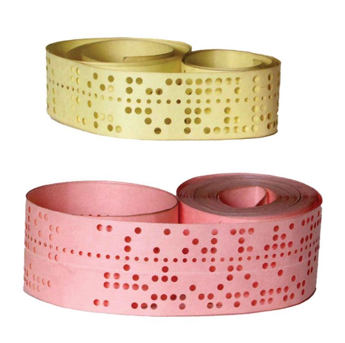
NC milling machines represented a significant advancement in technology, bridging the gap between the tracing stylus and fully automated CNC systems. NC machines relied on a combination of preprogrammed instructions stored on punched paper tapes and mechanical control systems to guide cutting-tool movements. The name “punch tape” comes from the holes punched on the tape used to convert programming information to binary data.
Punch tapes typically look like strings of paper with multiple lines of holes. The tape could be made of several materials—paper tape, with its low cost, was common. However, plain paper lacks durability. Stronger tape materials suitable for higher production use included mylar-reinforced paper.
Each line on the tape featured either five or eight holes, with each hole representing a bit of information, and each line representing a byte. NC machines used a light system to convert the hole pattern into information.
As the tape fed through the tape reader, the machine’s control system interpreted the punched holes to execute the programmed instructions. Each hole corresponded to a specific movement or action, such as positioning the cutting tool, adjusting the feed rate or changing tooling.
Based on the instructions read from the tape, the machine’s mechanical components, including motors, actuators and positioning systems, would move the cutting tool along the X, Y and Z axes as specified in the program. The cutting tool then removed material from the workpiece according to the programmed tool paths and other machining parameters.
Occasionally, operators needed to intervene during the machining process to change tools, reposition the workpiece or adjust machining parameters. Manual intervention became necessary due to the limited automation capability of NC milling machines.
CNC Technology
CNC machining uses computer controls to create 3D shapes from various materials. It provides precise control of cutting tools along multiple axes to remove material from a workpiece according to a digital design.
Using computer-aided manufacturing (CAM) software, the digital 3D model is converted into a series of toolpaths. Toolpaths define the precise movements of the cutting tool relative to the workpiece to achieve the desired shape and surface finish. CAM software calculates the optimal toolpaths based on tool geometry, cutting parameters and material properties.
The CNC machine reads the toolpaths generated by the CAM software and translates them into precise movements of the cutting tool along multiple axes. The machine’s control system regulates spindle speed, feed rate and cutting depth to achieve optimal machining conditions.
During the machining process, the CNC machine continuously monitors various parameters, including tool position, spindle speed and cutting forces, to ensure accuracy and reduce errors. Feedback sensors and control algorithms adjust machine parameters as needed to maintain optimal cutting conditions, negating the need for operators to intervene.
From the humble beginnings of the Keller tracing machine to the advanced CNC milling systems of today, the history of milling showcases human ingenuity and technological progress in the field of manufacturing. Each milestone in milling technology has brought us closer to the realization of precision, efficiency and versatility in shaping materials.
Future Technology
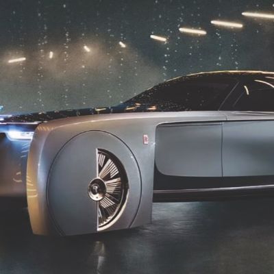
While traditional subtractive methods such as milling long have been the dominant approaches to machining, the emergence of additive manufacturing (AM), or 3D printing, has introduced new possibilities for fabrication of dies and molds. AM complements subtractive techniques by enabling the layer-by-layer deposition of material to build up complex 3D shapes directly from digital designs. While AM offers advantages in certain applications, 3D milling often is used in addition to produce the final shape to high-precision and high-quality surface finishes.
The future of 3D milling promises further advancements driven by ongoing innovation in machine technology, material science and digital design. The integration of advanced sensing and automation technologies can enhance the efficiency and accuracy of machining processes, while new materials and tooling techniques will expand the capabilities of 3D milling to tackle even more challenging applications. The convergence of 3D milling with other digital manufacturing technologies, such as robotics and artificial intelligence, holds the potential to unlock new levels of productivity and customization in die and mold manufacturing. MF
Technologies: Additive Manufacturing, Tooling


 Joseph Keller, a mechanical engineer, eventually constructed machines for use by the company, which, in 1930, merged with Pratt & Whitney. One such machine, the Keller duplicating machine, a tracer-controlled, horizontal milling machine, duplicated molds and dies. The design of the electric tracer distinguished Keller from other milling machines because it allowed greater precision of patterns and, therefore, produced more accurate dies and molds.