Die-Setup Procedures
August 29, 2024Comments
In the June/July issue, I discussed the importance of die and press cleanliness, as well as die alignment, ram lowering and clamping procedures. Here, I’ll discuss procedures for setting passline height, starting the material into the die, and setting timing and pilot-release points. I also will cover some final die-calibration procedures.
Setting Passline Height
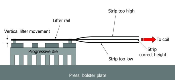
 Passline height, also known as feedline height, is the height at which the coil material feeds into the die. Ideally, stampers set passline height to the same height as the strip lifter system when in its idle or up position. Avoid feeding downward or upward into the tool. Regardless of the strip’s vertical travel, take care to set passline height at the level at which the material enters. Setting passline height at the midpoint of the strip’s vertical travel most likely is an attempt to compensate for an incorrect pilot-release setup.
Correctly setting passline height helps keep the material straight and flat. Straight, flat material is stiff and less likely to buckle or fold onto itself during coil feeding (Fig. 1).
Feeding Material Into the Die
Keep in mind that statistically speaking, the most severe die damage occurs when introducing, or threading, material into the die. Therefore, this is a critical stage of die setup.
 Starting the material at the wrong point in the tool can result in half hits, half cuts and half forms. This may result in severe unbalanced forces within the die, which can cause severe tool damage.
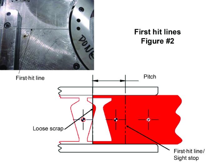
When threading the die, take care to properly feed up to the correct strip-starting position in the die—often called the first-hit line. It can be a solid stop such as a pin or pitch stop block, or it might be a simple line drawn, ground, or scribed on the die.
After the die has completed its first cycle, inspect the lower and upper die sections for loose scrap. Many dies produce small pieces of “startup scrap” produced during the strip-starting process. These small pieces of scrap tend to stick to the faces of cutting punches, pads and strippers. Failing to remove loose scrap from the die will result in the material being doubly thick, which also can result in die damage (Fig. 2).


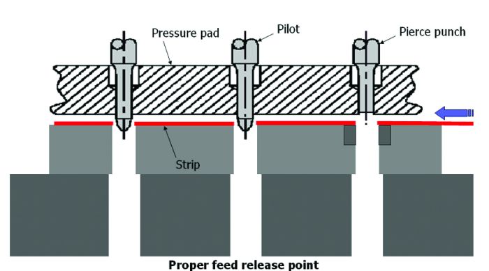
 The feed release must be timed so that the bullet nose of the pilot enters the strip, but the full pilot diameter does not. To determine this point, inch the press downward until the very tips of the pilots begin to enter the strip. Once you’ve established this point, note the degrees on the press stroke and set the pilot release to let go of the strip at this point. Program or adjust the pilot release so that the material or strip remains fully unclamped (feed rollers in the open position) until all of the work has been performed in the die and the strip has been returned to the proper feeding level (Fig. 3).
 Webinar