• Is the pitch length—the distance between the pilot holes —increasing or decreasing as compared to the designed pitch length?
• Are stretch flanges splitting due to a mismatched cut?
• Are extrusions splitting due to a burr or misaligned punches?
• Is the die hitting too hard or not hard enough?
• Does the die hit level in all of the stations?
• Is die timing correct when the die is fully loaded?
• Do cutting clearances change when the die is fully loaded?
Piloting Problems
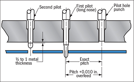
Perhaps the most misunderstood part of die setup is properly setting feed-release timing. If not set properly, the strip material may slide forward or backward after the grip rolls open and before the pilots have entered the pilot hole. This will be evident in the die strip, as the pilot holes will appear distorted or heavily marked on one side where the pilot tried to pull the strip back into progression. To improve this situation, consider making the first pilot with an undersized nose that is longer than the other pilots (see the accompanying figure).
Also, verify that the feed rolls open only after the tip of the longer pilot has entered the pilot hole deeply enough to prevent the strip from sliding backward, but before the full-sized pilot has completely entered the material. If the feed rolls open too late, the pilot punch can break off, distort the hole in the strip or prematurely wear. The feed rolls should close at the last possible moment, just before the full-sized pilot diameter pulls out of the strip on the upstroke.
Carrier Stretching
In strips designed with stretch carriers, be sure to closely inspect the strip to ensure that the stretch-loop radii are as large as practical. Sharp corners or small radii will concentrate bending stresses, making those the first points to fail when the carrier flexes.
 If the strip carrier has stretched permanently, the parts may be progressing too far off progression to fit properly onto the next station. When the strip has two carrier webs, in some cases only one carrier may be stretched. This condition will induce camber in the strip, causing it to veer to one side.
Note: This type of camber differs from edge camber imparted by the coil-slitting process.
If the carrier strip has a permanently stretched carrier web, it can be shortened to its correct length by forming a small rib or dimple in the carrier. If a center or one-sided carrier develops camber, the strip can be straightened by dimpling or scoring one side of the carrier. Design the dimpled and scoring features so that they are easily adjusted in two directions: sideways for position and vertical for depth.
Edge camber in as-received coils can cause the strip to bind in the guide rails, which guide the material during the feed cycle. This binding may cause the carriers to bend, distort or buckle, resulting in short feeds. If rubbing is evident on the slit edge of the progressive die strip, it might help to relieve the guide rails positioned between the workstations, and maintain tighter control at the working stations.
Another option is to eliminate camber by trimming both sides of the coil at the beginning of the die. These notches also can serve as pitch-control notches to prevent overfeeding.
A less-obvious cause of carrier-web stretching is roll pressure in the feed system. In general, the pressure on the feeder rolls should be set as high as possible without causing damage to the material. High roll pressure allows the feeder to accelerate aggressively without the material slipping. However, excessive feed-roll pressure can induce edge wave in the material.
When a die closes on material with edge wave—especially thin materials—the pressure provided by the stripper plate will flatten these waves, causing the carriers to increase in length during the die operations. When the die opens, the waves return to their original shape and the carrier will become shorter again. This condition can create all kinds of in-process variation that can be very difficult to identify, especially if one is not looking for it. MF
Industry-Related Terms: Bending,
Burr,
Camber,
Center,
Die,
Edge,
Forming,
Plate,
Stripper,
Strips,
WebsView Glossary of Metalforming Terms Technologies: Coil and Sheet Handling