Understanding Horizontal Forces in Stamping Dies
March 25, 2020Comments
The downward motion of a press ram applies a vertical force onto a die assembly mounted in the press as well as the workpiece inside of the die. The vertical force is expressed in terms of tons-force (tonnage) or kiloNewtons (kN).
 It is common practice to estimate vertical forces in a die assembly before starting a die design. Knowing these forces allows the die designer to determine thicknesses for die shoes, forming pads and dies steels in order to minimize deflections in the die. Estimating these forces also helps determine the size, quantity and spacing for any parallels required to achieve the desired feedline and die shut heights.
Before the die components can be designed, considerable knowledge is required about the forces acting on each of the individual components. The vertical forces must be analyzed to determine if horizontal forces or side thrusts, also called force vectors, are created during the cutting and forming processes. Horizontal forces inside of the die often cause many alignment-related problems.
A force vector represents a force with magnitude and direction. This contrasts with simply giving the magnitude of the force, known as a scalar quantity. For example, instead of saying that the force is 2 tons (scalar), we say that the force is 2 tons vertically toward the press bed (vector).
Horizontal Forces in Cutting Operations
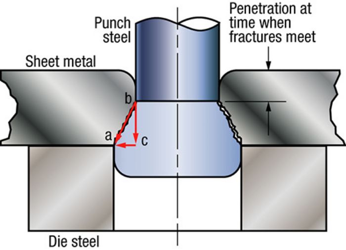
A simplified example of a force vector in a stamping die is depicted in Fig. 1. Triangle abc represents the physical relationship between a punch and die where the maximum shear load occurs before the slug fractures. Side ac represents the punch-to-die clearance. Side bc represents the sheet metal thickness through the fracture zone (i.e., the thickness of the sheet minus the punch-penetration depth). This same triangle also represents the force distribution in the cutting process. Side bc represents the vertical cutting force and side ba the resultant horizontal force.
Acquiring the vertical force from a strain gauge (force monitor) or calculating it with known shear strengths, a ratio can be used to find the horizontal force:
Clearance = Horizontal Force
Fracture Length Cutting Force
 Given precise die alignment and equal cutting clearance around the hole, the opposing horizontal forces balance out. A punch misaligned by 0.0015 in. would result in a horizontal force on one side of the punch of 503 lb.-force (0.25 tons) and 681 lb.-force (0.34 tons) on the other. Should the force differential be great enough, the punch point could deflect toward the lower-force side of the hole, worsening the misalignment condition.