 The use of cams, especially aerial cams, further complicates the timing sequence due to their travel distance, stripper-contact timing and increased travel distances of other components due to the vertical heights of the cams.
Understanding Travel Distances
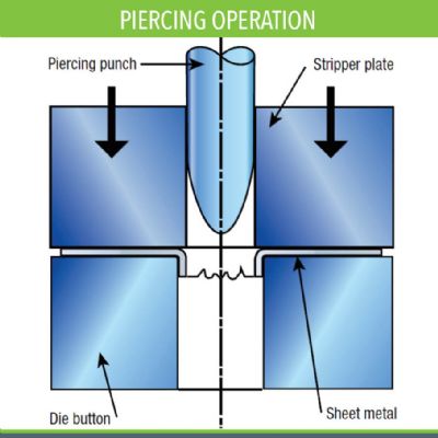
Work travel describes the distance that the punch works on the part material. For drawing operations, work travel equals the distance from punch contact with the blank to the bottom of the punch stroke. For cutting operations, work travel is the distance that the punch travels past the part material to the edge of the die steel.
With the die in the open position, the pressure pad and strippers must travel beyond the punch steel. Otherwise, the working components of the die will contact the part material on the downstroke, before the pressure pad and strippers securely hold the strip with the correct amount of pressure. On the upstroke, the pressure pad and strippers must remain in contact with the part material until the punches fully retract. This means that the pressure-system travel must always exceed work-travel distance.
High-Speed Applications
Small parts—for the electronics industry for example—almost always feature complex forms, and those forms generally have tight tolerance requirements. Forming at high speeds becomes more difficult with the need to always keep the stock strip straight throughout the tool—no lifting of the strip off of the die surface. This requires the use of form punches that raise from the bottom of the die and then return in order to allow feeding of the strip.
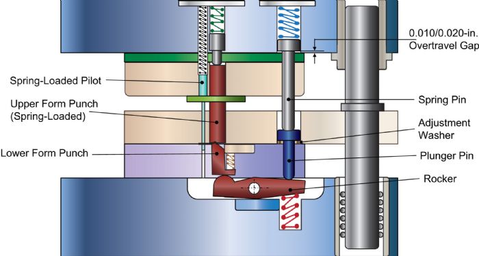
Fig. 2 shows a bottom-action form station. The upper spring-loaded form punch contacts the strip before the lower form raises. A rocker that pivots on a pin as well as a plunger pin activate the lower form punch. This pin has an adjustable washer under the head; washer thickness can be adjusted to suit the desired travel distance of the form and to facilitate springback compensation. A spring-loaded pin activates the plunger pin. Notice that this pin’s function is to provide a small amount of over-travel to accommodate small changes in shut-height variations that occur due to press setup, press speed and press temperatures.
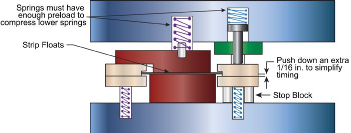
Keep in mind that the amount of spring pressure required to form even simple, thin parts can be considerable. The best option: large springs with ample free length and preload. The die layout will be longer due to the need to make room for the larger springs and rocker motions, but smooth strip feeding and consistency of the forms will make the longer die assembly an asset, not a liability.
Die Maintenance
When sharpening the cutting punch, always document the exact amount of material removed during grinding. To maintain die timing, place a shim, equivalent to the amount of material removed during grinding, under the punch holder. When doing so requires more than three shims, combine them into a single shim of the exact same size. Never use more than three shims under the punch holder.
When regrinding form sections, keep a precise record of the amount of material removed and the thickness of the shim—should this shim be lost, a properly sized replacement quickly can be made.
Often, shimming of die sections to solve one problem results in another problem. This can happen when not shimming punch holders as required. When this occurs, the press operator may adjust the press shut height downward to ensure a complete cut. However, the part-number stencil will again hit too hard and the setup person must remove another shim from under the stencil so that it appropriately marks the stamping.
The hidden danger here: shut height, set too low, causes the form steels to hit too hard. The hard hit on the forms produces an acceptable feature in the part—so no adjustments are made—but the condition generates unnecessary tonnage that can damage the die or press. Lastly, the stencil block now is out of time with the form stations, even though it marks the part as desired.
A thicker next coil compounds the above-mentioned problem. The thicker material requires removal of another shim from behind the stencil. The forms are hitting so hard now that the tonnage monitors keep tripping, shutting down the press. Because the formed features still “look good,” an operator adjusts the high limits on the tonnage monitor upward as tonnage being generated resides within the press’ capacity—but potentially damages the die.
All of this occurs because, after sharpening a punch, someone didn’t shim the punch holder to maintain die timing. MF
Industry-Related Terms: Blank,
Center,
Compress,
Die,
Drawing,
Edge,
Form,
Forming,
Grinding,
Plate,
Ram,
Shut Height,
Stripper,
Stroke,
Surface,
Thickness,
ToleranceView Glossary of Metalforming Terms Technologies: Tooling


 As the die begins to close, the upper stripper plate contacts the stock strip and any guide-rail lifters used to raise the stock strip above die level—usually to facilitate feeding over form stations. The stripper face pushes the stock strip down until it is held against the lower-die steel. The guide-rail lifter has over-traveled slightly to ensure the presence of a gap between the top and bottom surfaces of the lifter (Fig. 1).
 Webinar