 Assess and address ram tipping when creating the die strip layout. Unfortunately, die designers often overlook or misunderstand this step, resulting in strip layouts that position the center of the progressive die with the center of the press ram. Many dies are designed, manufactured and installed in presses without consideration given to centering the load due to designers misunderstanding the negative effects of off-center loading on part quality and die life.
Centered Load and Centered Die—Not the Same Thing
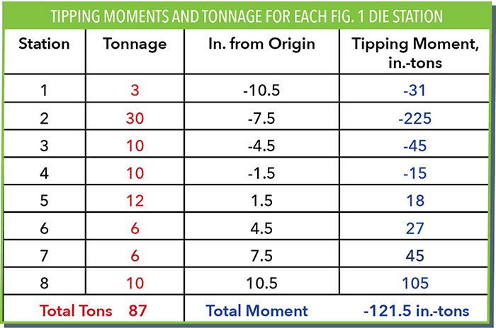
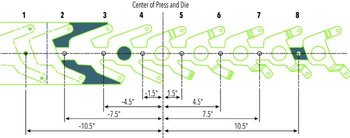
The strip layout in Fig. 1 represents a process for an eight-station progressive die. Tipping moments can be calculated by multiplying the die forces by the distance from the centerline of the press ram. Using the center of the press as the origin, distances to the left are assigned negative values while distances to the right are positive. In a perfect world, the sum of the moments equals zero, indicating balanced forces across the press ram.
The table, Tipping Moments and Tonnage for Each Fig. 1 Die Station, summarizes the forces acting on each station in the strip layout and their distances from the center of the press. The table’s last column shows the resultant tipping moment for each station. In this instance, the sum of the moments equals -121.5 in.-tons. The negative value indicates that the center of the load resides to the left of the die centerline.
Dividing the total tonnage by the sum of the moments gives us
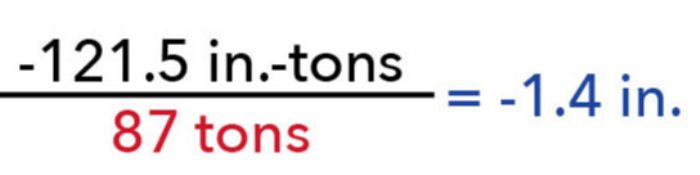
The center of the load resides 1.4 in. to the left of the press/die centerline. Shifting the centerline of the strip 1.4 in. to the right of the die centerline balances the loads. For a die already constructed with the strip on center, clamping the die in the press with the die centerline 1.4 in. to the right of the press ram centerline also balances the load. In both cases, the center of load now positions on the center of the ram.
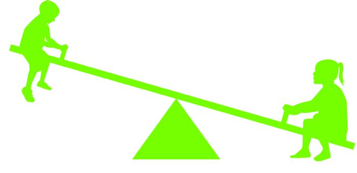 This is analogous to two children of different weights sitting on a seesaw. In Fig. 2, both children sit 3 ft. from the center fulcrum and the seesaw tips in the direction of the heavier child due to the larger tipping moment: 135 ft.-lb. vs 165 ft.-lb. Positioning the heavier child to 2.5 ft. from the fulcrum (Fig. 3), offsets the tipping moments: 138 ft.-lb. vs. 135 ft.-lb., thus balancing the seesaw.
 It is not necessary to perfectly balance all the forces across the ram. The press structure and die guiding systems can handle some off-loading conditions. In our example, a press structure designed to handle more than 121.5 in.-tons of off-center loading requires no action.
Interpret Tonnage Readings Properly
Even when the sum of the moments equal zero, some tipping may occur as the moment forces may not occur at the same time or same ram position. This becomes problematic when press technicians rely on peak-tonnage results displayed on tonnage monitors to verify balanced loads.
Keep in mind that forming forces may occur 0.5 in. or more above the bottom of the press stroke, while forces generated by punching and blanking occur near bottom dead center. The forces are numerically balanced, but the ram still tips due to loads produced at different times (ram position) in the press stroke. When using tonnage monitors to balance loads, use load signatures to determine when these peak loads occur.
Uneven distribution of working forces within the die may make balancing loads impossible for many processes, especially when using progressive dies, if these loads were not considered during the design phase.
Tell-Tale Signs of Off-Center Loading
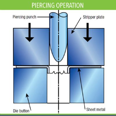
Tell-tale signs of off-center loading include chipped, bent or broken punch points; sheared die buttons or die matrices; and uneven shear (cut) bands inside of holes or other punched openings.
Also, look for uneven solder checks on set blocks. Progressive dies usually contain four or more set blocks mounted to the die shoe. Solder thicknesses that vary from left to right also may indicate a die-timing issue. For example, a form block shimmed too high, preventing the die from closing onto the set blocks, can force the ram to tip. Other indicators include an increase in needed die maintenance or repair, and increased press-maintenance costs. Off-center loading also compromises the dimensional consistency of the stampings being produced. MF
Technologies: Tooling


 For example, assume that the punching action in a die generates a 100-ton load on the left side and a 50-ton load on the right side, with both punches equally spaced from the press centerline. This situation generates a large left-to-right tipping of the press ram because the load on the left side measures twice that of the right.
 Webinar