Increasing Press Speed and (In)Efficiency
March 30, 2023Comments
Press shops face constant pressure from customers to reduce manufacturing costs. A common method: Increase strokes/min. on the stamping press. But, before turning up the speed dial, understand the effect it can have on the overall stamping process.
Increasing press speed can amplify issues related to coil feeding, scrap removal and tool deflections. The forces needed to punch and trim at higher speeds can increase unloading forces—snapthrough—that shock and break tools, and sometimes presses.
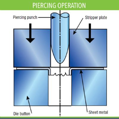
Hole punches may fail prematurely at higher speeds if not properly engineered. Common practice has been to use 5-8 percent of stock thickness per side for cutting clearance. This clearance produces an acceptable burr height and provides reliable slug control. But as stamping speeds increase, tight clearances can be a source of increased downtime and tool maintenance due to wear, galling and breakage.
Staggering cutting punches at heights equal to or slightly less than the shear-band depth in the holes that they produce greatly reduces impact and unloading shock. This method allows the succeeding group of punches to contact the part material before the slugs from the preceding group of punches break out of the strip. The unloading energy from the first group of punches drives the next group through the part material, reducing the unloading loads. Using the shear-band depth for the punch-offset distances—instead of an arbitrary percentage of material thickness as generally employed—also reduces punch entry into the die matrix, which helps to minimize punch wear.
Tight clearances produce hole diameters slightly smaller than the punch-point diameter, creating a press-fit condition between the punch and work material with each hit. The resulting interference fit causes friction that generates heat. Increasing press speeds generates more heat and decreases tooling contact time along with any cooling that might be afforded by the tooling. Smaller-diameter punches also have less ability to dissipate heat and are prone to overheating. This can result in a loss of hardness, reduced wear resistance and dimensional instability.
Speed Increases Stress on Press Components
Now consider a typical mechanical press cycle: The ram accelerates from rest at top dead center until it reaches a maximum velocity at 90 deg. of rotation. The press slide then begins to decelerate as it approaches the bottom of its stroke. Because the ram motion creates large inertia forces—the greater the press speed the greater the inertia force—the ram wants to continue its downward travel as the press crank tries to accelerate it in the opposite direction on the upstroke.
This places tremendous stress on press components, especially the pitman connections. Depending on the magnitude of inertia forces and the rigidity of the machine design, the pitman can elongate, effectively reducing shut height. Shut-height reduction introduces additional stresses impacting the large end of the pitman on the crank journals, producing additional frame deflections.

 Webinar