Take What You Know About Stamping Presses
August 1, 2012Comments
...and throw it out the window, because servo-driven mechanical presses are becoming the rule, not the exception. As a result, the rules of the stamping game have changed, forever.
The advent of servo-drive technology in mechanical stamping presses has changed the rules of engagement between metalformers and their customers. Simply, early adopters of servo presses soon will—if they haven’t already—leapfrog their competitors in the race to gain new customers.
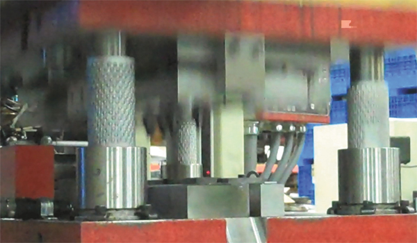
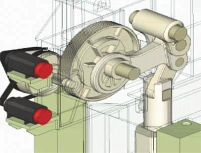
Throw everything you know—or think you know—about the ability to control a stamping press’s slide motion and the types of metalforming operations that can be performed under ram out the window. With servo-drive presses, metalformers can program stroke and slide velocity in any imaginable combination, to optimize performance for a given material and operation, whether it be blanking, coining or deep drawing. Servo motors, installed in place of the traditional flywheel/clutch drive train, allow the output shaft to be rotated in both directions. The press ram can stop precisely at any given position, and change speeds on a dime.
As explained in a recently published book from ASM Intl., by authors from Caterpillar Technical Center and The Ohio State University (Sheet Metal Forming—Fundamentals, copyright 2012), metalforming-process designers around the world are being introduced to a whole new world of opportunities:
• Dwell anywhere in the stroke, and at bottom-dead center (BDC), under full tonnage without energy loss.
• Reduce cutting speeds and snapthrough forces without compromising productivity.
• Control forming velocity to minimize friction and heat generation.
• Reduce impact speed and noise.
• Make multiple hits on the workpiece at or near BDC to reduce springback, useful when stamping advanced-high-strength steels for example.
• Allow assembly and other secondary operations to occur under the ram, thanks to the ability to slow down or stop the press slide at any point in the stroke.
 |
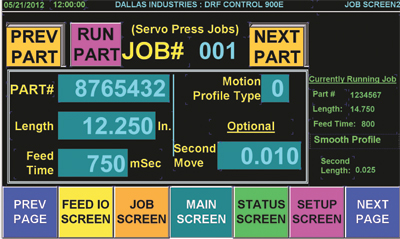 |
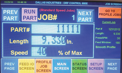
| As these images from Dallas Industries illustrate, while the control for a coil feed installed on a conventional mechanical press (left) works from data input for feed length and speed (as a percentage of maximum), the feed control for a servo-drive press (right) is more interested in feed time (in msec.) and motion-profile type. | |
As one early adopter of servo stamping press technology recently stated: “As a result of the flexibility afforded by servo-press technology, we’ve been able to quote jobs we could not have considered in the past. For example, we now can pause at a given point in the press stroke to perform laser welding or component insertion…adding value for our customers and allowing our company to compete in the global economy.”
Avoiding Speed Constraints
|
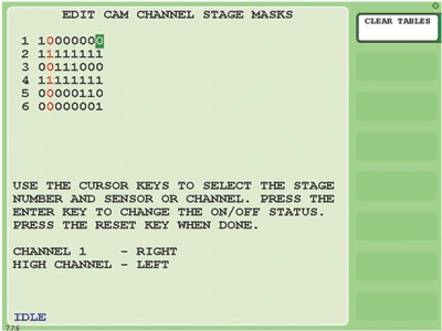
A—This screen allows the user to select which cams fire on which stages. The stages are listed on the left column (1-10)—in this example, only six stages are being used. The series of 1s and 0s indicate which cams will be active on each stage. The control stores separate sets of masking information (for sensors and cams) for each job. |
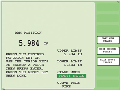 |
B—This programming screen addresses ram position. The user can select the stage mode (single or multistage) and the motion-curve type (sinusoidal, linear or one of three different asymmetrical curves). He also can set the upper and lower limits. |
|
|
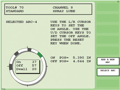
C—Here we see the programmable limit switch (cam) timing for channel 8, which—according to the mask shown in screen A—will turn on during the second, fourth and sixth stages of motion. |
 |
D—On this main run screen the operator can view the current stage, ram position and upper and lower ram limits. A function key allows him to start the self-learn process that allows the control to learn the stage motion for the job. |
 |
E—This screen shows the upper and lower ram limits for each programmed stage (six stages shown here). These values can be user-entered or can be automatically created as a result of the self-learn process. |
Double (or more) the output without sacrificing quality—what stamper would not want to do that? But the reality of such a notable boost in output means there’s less time to perform all of the operations that go along with forming—feed and sensing, for starters.
“Flexibility, speed and throughput are what allow stampers to justify the move to servo presses,” says Jim Ward, general sales manager of press-feed system supplier Coe Press Equipment. “The challenge for feed manufacturers, as well as manufacturers of other ancillary pressline equipment such as part-transfer and die-sensing systems, is to provide speed while maintaining accuracy. We’re speed-limited based on the drives and motors available, as well as by the ability to securely grip the material as it feeds. That’s where the industry will see technology advances related to feed equipment—so we’re not the speed constraint.”
Speed constraint becomes most critical when metalformers operate a servo press in pendulum mode. “In this operating mode, completely unique to servo presses, we cannot only be concerned with acceleration and feed rate, and just play beat the press,” says Willie Chacko, CEO of feed supplier Dallas Industries. “In pendulum mode, there’s often precious little time available for us to fit in our motion profile to index the material before the next press stroke.
“With a conventional press, we run the feed in impulse mode,” Chacko continues. “The press control says feed and we feed. Then we signal when the feed is complete so that the press can stroke. Now we’ve learned and adapted the technology so we can synchronize our motion with that of the servo press, and still develop a smooth motion profile in the time allotted.”