Daniel Schaeffler Daniel Schaeffler
President

Sims Aren't Everything

December 1, 2018
0
Comments


Simulation has made inroads into the metalforming community as an ideal way to predict what will occur when sheetmetal of known properties is subjected to known deformation forces. It saves days of trial-and-error, helping to evaluate what-if scenarios associated with variables such as metal grade and thickness, binder and addendum designs, and blank shape.

It is, however, risky to blindly accept simulation output as infallible. Simulations are accurate, but only to the extent that the inputs represent reality as opposed to a simplified estimate of reality. Simplification begins with the imported CAD file. No doubt that the design in the file was accurate at one time, but most likely that dates back prior to tool construction. Once fabricated, tooling likely undergoes some period of adjustments to achieve a good part, such as, for example, using spotting blue to check a bearing. By grinding anywhere on the tool and especially on a draw bead, you’ve made a permanent change to the metal flow in that area. Best practice: Re-scan the tools once they produce good parts. This provides a record of the tool surface responsible for today’s parts.

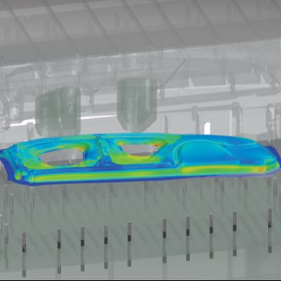
Recent years have seen more attention paid to the weight of forming tools, with the focus on making them lighter. This has led to structural analyses of the tooling to ensure mass only where it contributes to functionality. The expectation is that reduced mass does not impact tooling stiffness, and what remains is the minimum functional structure. This may be an acceptable strategy should the tooling surface be retained during the buyoff process. We know that issues with springback increase with stronger sheetmetals. In the hands-on process of minimizing springback during physical tryout, recuts become inevitable. Since each iteration removes tooling metal, tooling stiffness can be affected. In most simulations, assumptions include rigidity of the tool, ram and bolster, with no deflection under load of any component. But rarely does this accurately represent reality.

The Modulus of Elasticity (E), an important input into forming simulations, is critical to obtaining an accurate assessment of springback. Textbook values for E include 210 GPa and 70 GPa for steel and aluminum, respectively. However, these values change based on specific grades or alloys. These textbook values typically are determined in tension. However, regarding springback, the modulus from unloading should be considered. According to some studies, the unloading modulus may be 25 percent less than the modulus determined during loading. Furthermore, the modulus changes based on the level of plastic strain seen in each region of a part.

Density represents another parameter where, previously, textbook values may have been sufficient. Steel density does not vary much between mild-steel grades, but higher-strength steels use non-iron elements in greater amounts, which changes the alloy density. Aluminum alloys in the 5XXX or 6XXX series achieve their properties with different alloying approaches, with the resultant density a function of the type and concentration of the chosen elements. The Aluminum Association Teal Sheets lists the density of different aluminum alloys.

Many simulations do not consider the effect of temperature when the assumption is made that room-temperature stampings remain at room temperature during the press cycle. When forming higher-strength alloys even under ideal conditions, the temperature at contact radii substantially exceeds room temperature. Work from Professor Altan’s R&D group at Ohio State University has shown that, in identical setups resulting in a maximum temperature of 120 F when forming mild steel, temperatures of 175 F were reached when forming DP600 and AA5182-O, and DP980 reached 210 F with DP1180 heating to 300 F, again under identical thickness and forming conditions. At these elevated temperatures, die sections will expand, which changes clearances and metal flow.

Although some lubricants are designed for higher temperatures, you may be choosing the wrong one if you think that you are performing only room-temperature stamping. Elevated temperatures seen at contact points can lead to lubricant burn-off, resulting in no lubricant at the most critical locations. Among other things, this accelerates wear, a circumstance not accounted for in the simulation.

Most simulation programs offer one input for a friction value, which we know varies across the entire part and is based on local conditions. Friction changes with contact pressure and temperature, as well with the lubricant additives active under those conditions. Different tests, such as Draw Bead Simulator, Twist-Compression or Pin-On-Disk, can determine friction. The resultant values differ as the test conditions differ. For steels, friction changes based on the galvanized coating. Not surprisingly, a hot-dip galvanized coating has a different friction than electrogalvanized or galvannealed coating. Since the surface morphology of any one of these coatings can differ between suppliers, friction can vary even within a given coating.

Your choice of material model is a required simulation input. Which one is best? Unfortunately, no one right answer applies to all metals and forming conditions. A natural tendency may be to use a model not requiring the entry of many parameters, perhaps one that uses only uniaxial-tensile-test values. While easier, these models are not as accurate.

More accurate models typically require results from tests not commonly performed. Without the correct data, people may choose values generated from other materials that may not be applicable for your particular product. Also, while tensile-testing procedures are very well-defined, results still differ from lab to lab. The test procedures needed for more complex models are not as rigorously defined as tensile testing, so variability in these tests are much more likely.

Finally, simulations offer a choice of what material properties to include. Some packages automatically vary the properties between low and high values, but if not using such programs, you should manually test the effects of different properties. The inclination may be to run worst-case examples, but it is important that your selection be realistic. Simply inputting low-end properties is not appropriate as our supplier cannot produce a sheetmetal with the lowest yield strength combined with lowest elongation and lowest n-value—low yield is associated with high elongation and n-value. While you may not worry about splits on a high-ductility metal, wrinkles are a concern, which, in turn, can restrict metal flow. Most forming simulation programs require r-value as an input. Not only does r-value change with orientation relative to the rolling direction, but the magnitude of this change is not consistent between grades. R-value changes with plastic deformation, which means that metal formability changes during the press stroke. Simulation software packages typically do not account for this.

Forming in the virtual press shop is an efficient way to test out variables that you might eventually see in production. Understand the limitations of your virtual press shop, and the impact of the assumptions made while developing a safe and robust stamping. MF

Industry-Related Terms: Grinding, Model, Plastic Deformation, Ram, Run, Stroke, Surface, Thickness, Alloys, Blank, CAD, Die, Draw, Forming, Functionality
View Glossary of Metalforming Terms


See also: Engineering Quality Solutions, Inc., 4M Partners, LLC

Technologies: Lubrication, Software

Comments

Must be logged in to post a comment.
There are no comments posted.

Subscribe to the Newsletter

Start receiving newsletters.