Add-On Software Tackles Specific Challenges
A 3D CAD package by itself, such as the SolidWorks software recently added by Wisconsin Metal Parts, is similar to a family doctor in that just as a doctor sees many different patients and treats a variety of illnesses, so, too, is the CAD software package used by people in a variety of industries designing vastly different things. But in the case of a family doctor, he calls a specialist for something very specific and complex, such as a patient requiring heart surgery. Likewise, 3D die-design software packages are specifically designed to address and streamline the nuances unique to die design.
While Wisconsin Metal Parts saw many benefits over its previous software after using its new parametric CAD software, the company saw the significant benefits of adding a specialized add-on, and chose to add Logopress3 die-design software, from Accurate Die Design, Inc., to complement SolidWorks.
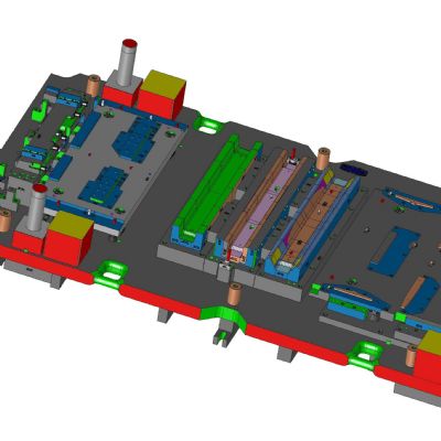
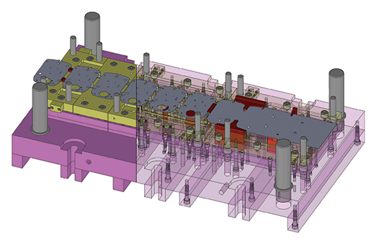
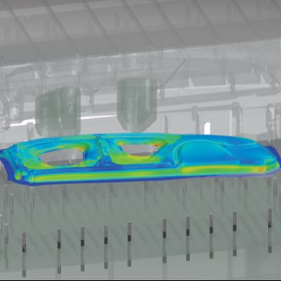
One benefit was the ability to use transparency to design more quickly and help prevent mistakes, then make the model solid in a matter of seconds for a design review. As the creator, the die designer easily can visualize and understand a transparent model, but visualizing can be difficult for others unless the model is made solid (Fig. 1). 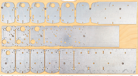
Fig. 3—Each of these three die designs had differing stock widths and progressions. The second and third designs were created by reusing data from the first design.
Is Parametric Software Really More Complex?
Parametric CAD software is viewed by some as being more complex than its direct-modeling counterpart. But complexity can make life easier, i.e., a car when compared to a horse or a bicycle. Or consider a wire-EDM machine. Until the 1970s, tool and die makers used band saws, mills and grinders to section die blocks and punches and so forth. While a wire-EDM machine costs significantly more than a band saw, mill and grinders, and certainly is more complex, at the end of the day the wire-EDM machine runs circles around the old-fashioned die-build method while, at the same, making die construction easier and more accurate.
Just as with a wire-EDM machine, most designers realize that the added complexity of parametric die-design software makes life much easier after the learning curve. Schwartz, for example finds significant benefits in the history tree found in parametric software, along with all of the relations between features and parts that are unavailable in direct-modeling software.
“That’s huge for me, being able to go back in time to make a change,” Schwartz says.
Schwartz also appreciates that all of the various parts in the die are individual part files existing inside of an assembly file, rather than the entire die assembly existing as a single file, as with direct-modeling CAD software. This allows for quicker and easier detailing, and each part file is ready for CAM without the need to separate the files from the single assembly file, a time-consuming task that Schwartz previously had to perform.
Reusing CAD Data Speeds the Process
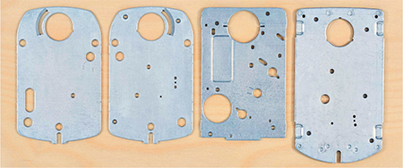
Recently, Wisconsin Metal Parts received an order for three dies to make four separate parts (Fig. 2). Each of the dies would share the common attributes of a station to coin the burr side of the material; guided strippers throughout, along with stripper balancers; backup plates throughout the top and bottom of the die; and sensors detecting feed length and stripper balance.
The first die would be interchangeable, used to produce two different parts. That die design (Fig. 1) features a progression of 4.150 in. and a stock width of 6.250 in. The company designed and 100-percent detailed this die in 54 hr.
For the second die design used to produce the third part (Fig. 2), Schwartz used a Logopress3 command called “Save as with new project name.” This command saves all part, assembly and drawing files with a new project number, job number or tool number to differentiate it from the first design. This allows the designer to reuse as much data as possible. After deleting the stock strip and related punches, the designer inserts the new strip layout and adjusts the parametric dimensions. Because of the parametrics involved, the designer easily can change the progression and stock strip width for this new die design. This second die design has a progression of 3.950 in. and a stock width of 6.000 in., differing from the first die. Wisconsin Metal Parts designed and 100-percent detailed this design in 18 hr.
The third die design, differing from the first two and the most complex, featured a pierced hole with the same diameter as the material thickness, as well as 10 cold-formed extrusions on the die side with diameters equal to the material thickness. This third die design, with a progression of 4.050 in. and a stock width of 7.000 in., was designed and 100-percent detailed in 30 hr. Fig. 3 shows strip layouts from each of the three die designs, each with a different stock width and progression.
Productivity Increases Still Unfolding
These designs showcase the power of parametric software. While Erschen appreciates that his staff now designs and details dies twice as quickly, he also sees additional benefits for the shop.
“We still create 2D detail drawings as before, but now our staff can open and work directly with the 3D models in our existing CAM software,” he says.
Erschen also notes that that the new software results in fewer mistakes. Next up, Erschen plans to expand communication across the shop through the die-design process by employing a free viewer and markup tool included withthe software. MFView Glossary of Metalforming Terms
See also: Accurate Die Design Software, Inc., LOGOPRESS
Technologies: Software
 Webinar