 Cobra Aero carried out the evaluation in its small-engine development test cell, equipped with a full AC dyno (with motoring capability) housed in an environmental chamber that can evaluate performance in temperatures from -40 to +150 F. The test team mounted the engine on a propeller stand, with the propeller spun in various rpm ranges and operating temperature controlled by air blown through the cylinder ducts. The team continuously monitored the cylinder-head temperature.
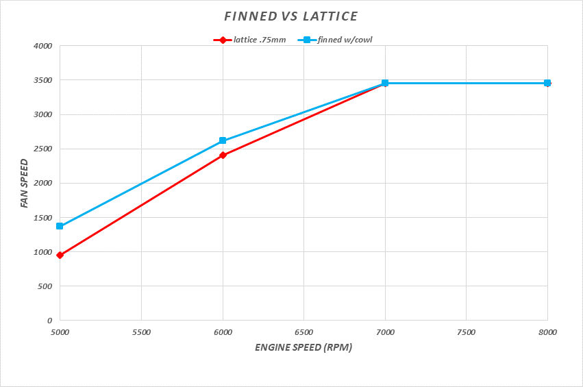
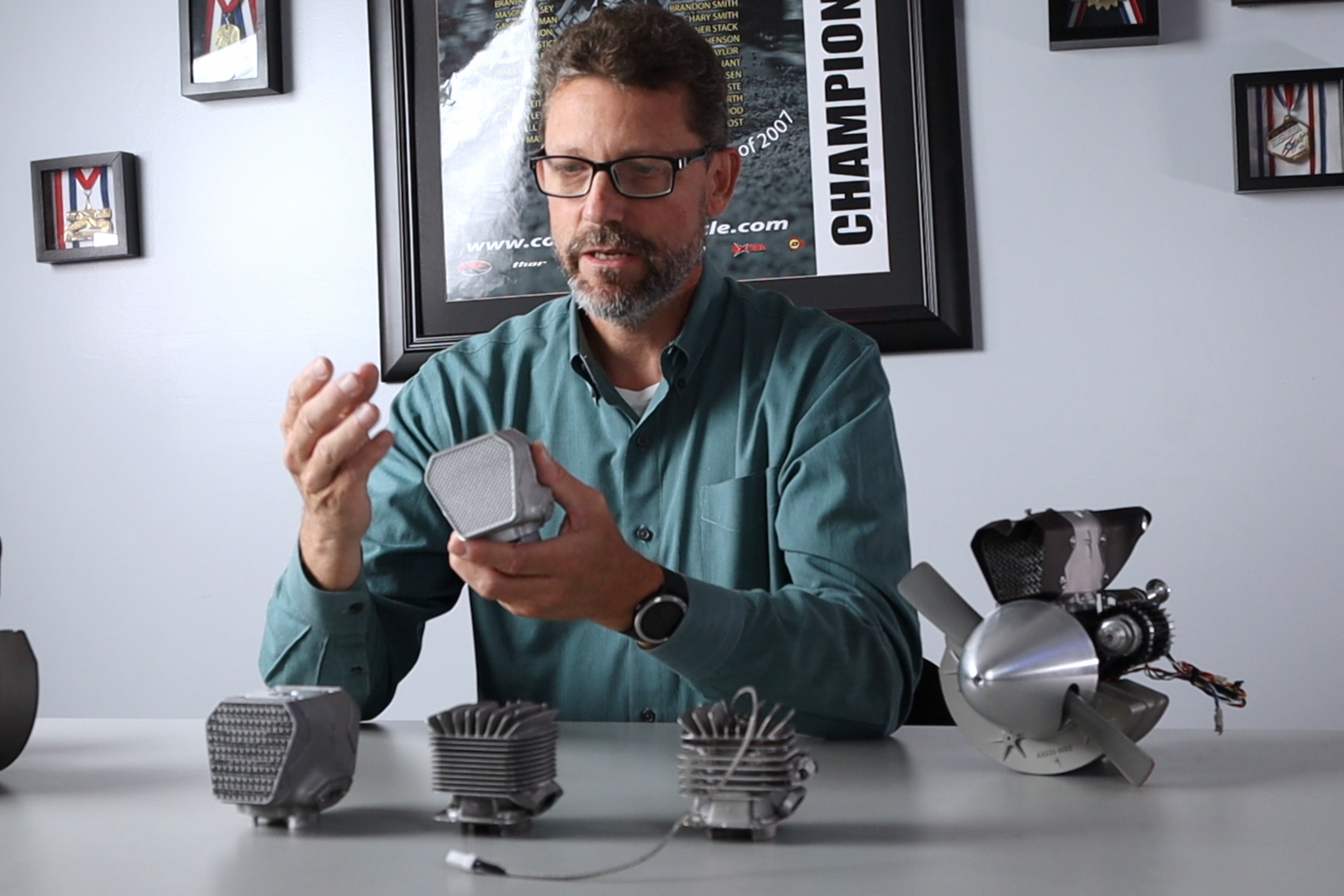
“Testing showed that the new AM lattice structure was more efficient at cooling than our previous fin design,” Hilbert reports (Fig. 2). “In every case, at every different rpm, less cooling air was required to maintain proper engine temperature. Going forward, we can make a smaller inlet to the cooling duct, resulting in a smaller frontal area on the aircraft. This means less drag on the aircraft for the same amount of cooling—exactly what we were hoping for.”

 The original finned cooling system itself is an AM-adapted, commercially successful design.
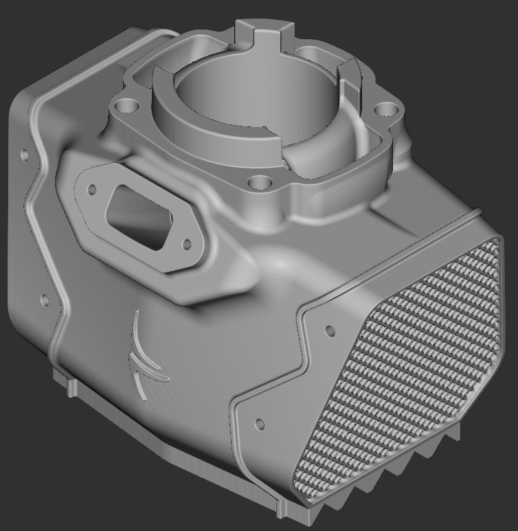
“The finned part that we’re currently shipping works wonderfully and prints beautifully,” Hilbert says. “But it requires a lot of post-processing due to almost as much support structure on the cooling fins as material in the part itself. And, all of those support structures must be removed manually after 3D printing.”
Complexities Abound in Designing for AM
When first looking for design alternatives to fins, Hilbert’s team became intrigued by the internal lattice structures employed in products across a variety of industries, from aerospace to medical devices. By hollowing out a solid aircraft bracket or a human joint implant, and filling the space with a lattice, honeycomb or gyroid structure, weight can be decreased and strength improved. The bonus: Self-supporting lattices do not require support structures during the AM build.
“It looked like an interesting technology to use on our engine cylinders for a couple of reasons,’” recalls Hilbert. “One, a lattice structure would be very print-friendly and two, it might allow us to tailor-fit heat transfer in a better way.”
Cobra Aero benefitted from a suggestion by Renishaw’s Kevin Brigden, a design-for-additive-manufacture (DfAM) specialist supporting Cobra Aero on development of the 3D-printed finned design, following the company’s purchase of a Renishaw system.
“We thought that we could use lattice structures available in nTopology’s nTop Platform software to simultaneously improve the printability of the component and also increase its performance,” Brigden says. “These motors are designed to be used in drones, where extra mass can take a particularly heavy toll on payload, range and performance. The fact that the generation of hundreds and thousands of different lattice shapes is mathematical, accomplished without having to create discrete, surface-based models such as with traditional CAD packages, meant that we could be much more adventurous with our designs for 3D printing.”
Software Eases Lattice Generation
 The team began using the software to generate different sizes of lattices and varying wall thicknesses of struts, running some computational-fluid-dynamics bulk-properties simulations to provide a rough idea of target lattice densities.
“The issue: The amount of pressure drop across the cooling duct relates directly to the amount of drag on the airframe,” Hilbert explains. “We needed to find that sweet spot with enough heat pulled away from the cylinder but without adding a tremendous amount of drag onto the entire structure―enabling the UAV to fly longer and more efficiently.”
|
Software Automation Simplifies Complex Modeling
BY GABRIELLE THELEN
|
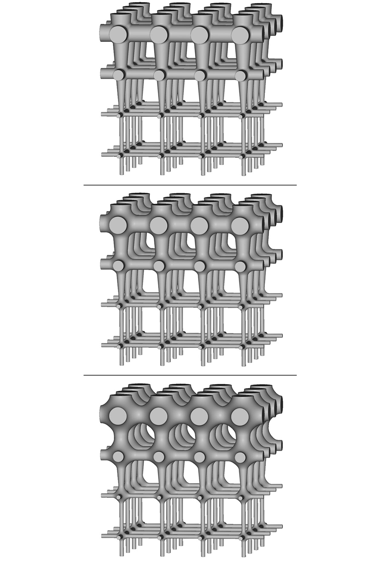
| Changing a blend-radius parameter, within computational-modeling software, applies a fillet between beams and connecting bodies in seconds and without failure. |
The ability to achieve unprecedented part complexity—particularly in the case of advanced-manufacturing technologies such as 3D printing—has reached a point where it has overextended the conventional CAD tools used for decades. Modifying a design, such as simply applying a fillet or round between nodes, beams and connecting bodies, can be tedious and often impossible with traditional design software. This low-value-added work slows down the engineering process and inhibits innovation.
The answer: software automation, calling for a system’s architecture to handle such tasks, and programming to repeat the necessary operations in the background.
Computational modeling takes that approach, solving the problem of low-value-added tasks. Based on a foundation of implicit algorithms and field-driven design, advanced platforms condense large-scale operations into mathematically expressed properties or variables that can be run automatically in reusable workflows, quickly—without a single model breaking.
|
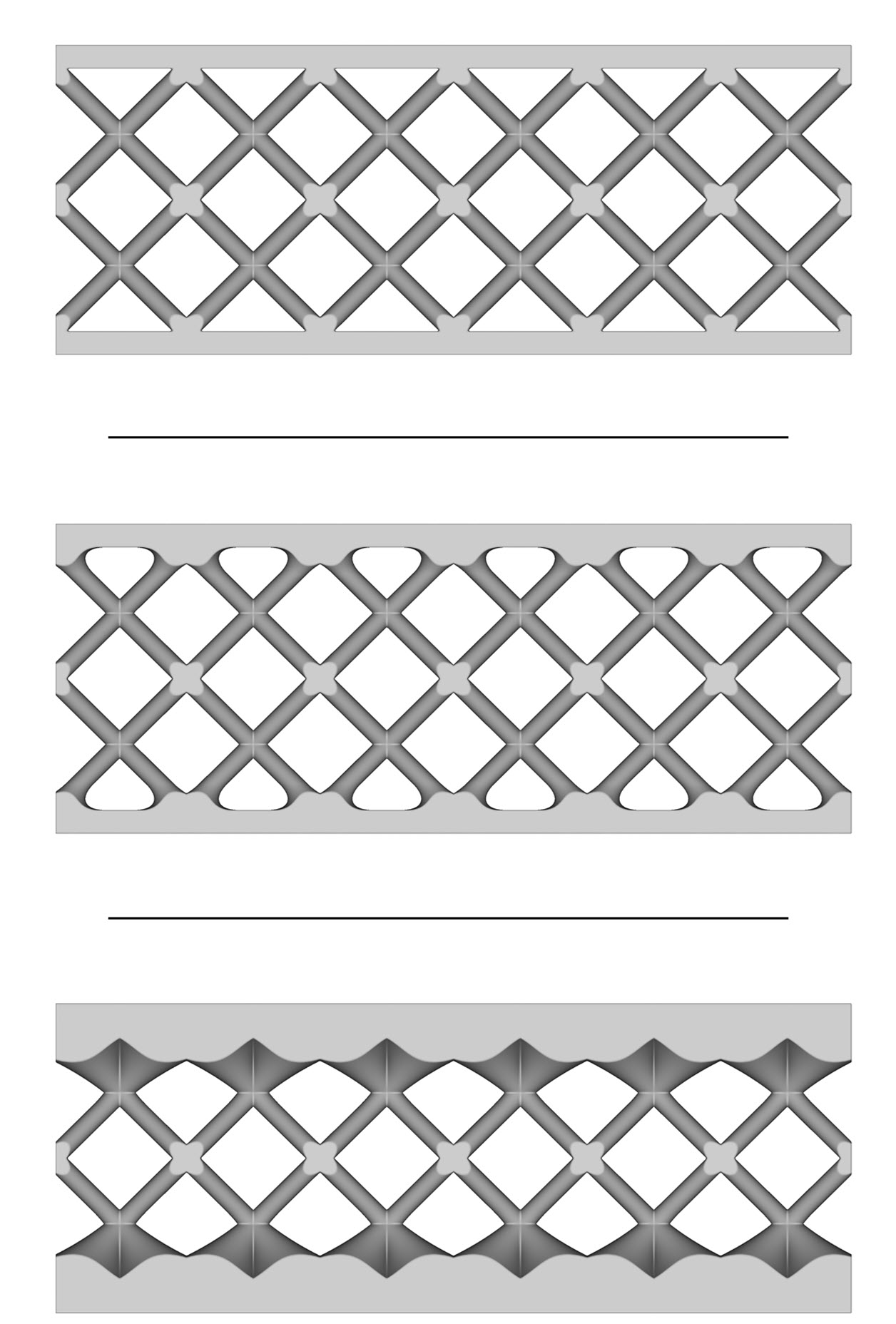
| Large fillet values, traditionally causing a model to complain and a model tree to fail, are made possible within computational-modeling software. |
Here we’ll focus on filleting, a tedious but necessary design task. The increased use of 3D-printed, internal lattice structures for lightweighting parts has produced an explosion of geometric creativity. However, along with the increased complexity comes an increase in difficulty of design when ensuring manufacturability.
For example, when employing shelling and latticing techniques for lightweighting, from a design for AM perspective, strive to have a solid connection between the lattice and outer skin to prevent delamination, which often only is visible once a part has been printed. This can be achieved through fillets, where the lattice struts connect to the skin.
The fillet structure reduces stress concentrations that can lead to delamination, by distributing stress more uniformly and over a broader area. Broadening or smoothing the surfaces and angles between features in a lattice with fillets provides additional benefits of promoting part durability and manufacturability.
Traditional 3D representation, on the other hand, requires a selection of all intersections before attempting to create rounds at all locations. Engineers, however, know the pain and frustration that this method can bring, not to mention the aggravation of a rebuild error when new fillet values simply will not recreate.
|
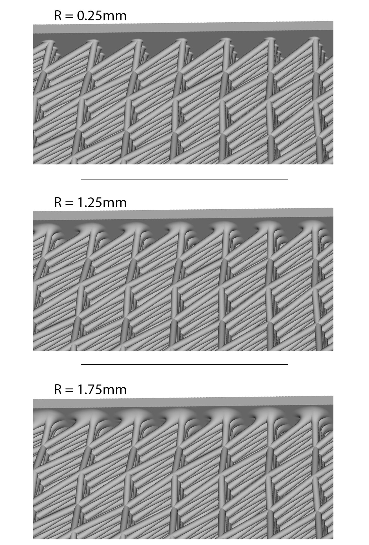
| Automated filleting is shown driving through one parameter—the fillet size across nodes within a lattice structure—and also varying fillet size when moving from the bottom to the top of the structure. |
In contrast, with advanced computational methods, large fillet values—which normally would cause a model to fail completely within a traditional CAD environment, due to interior surfaces colliding and intersecting—are easily achievable.
Because of the underlying implicit-data structure behind 3D-model representation in a computational-modeling platform, large-scale fillet operations can be condensed to a property or variable as part of a separate modeling operation. Operations traditionally seen as risky or fragile simply do not fail. Such a software platform eliminates the fear of model-tree failure and always will return a valid, solid model.
In this kind of system, automation thrives and engineers quickly can evaluate new concepts. By leveraging available advanced design controls, it is possible to automate filleting operations, reliably fine-tune a model in a matter of seconds, and continue undistracted with the goal of rapidly determining the best product variations possible and designing innovative parts faster.
Gabrielle Thelen is an application engineer at nTopology, New York, NY; 917/983-9257.
|
Using nTop Platform’s automated capabilities, Cobra Aero quickly filled in the lattice inside of the cylinder geometry and terminated it on a highly undulating surface. The team considered a variety of configurations, with the software readily handling all of the generated data.
“AM offers so much design freedom, but realizing that potential comes down to properly representing and designing geometry, which is what our software does,” says Jonathan Harris, lead application engineer for nTopology. “Our implicit algorithms and field-driven design capabilities give designers the ability to synthesize all different sources of engineering data on a single platform, choose how each influences their design, and easily and automatically change and rebuild to fit desired parameters.”
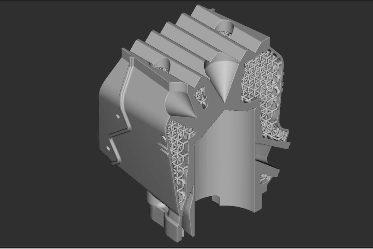
The software allows rapid consideration of different lattice structures, automatically filling in fillets (see Software Automation Simplifies Complex Modeling sidebar) to broaden and smooth strut intersections and connections to the part skin (Fig. 3). This distributes stress uniformly, according to nTopology officials, reducing concentrations that can lead to delamination, and promoting manufacturability and durability.
“By the time we were done, our models had evolved to the point where they were simply beautiful,” says Hilbert. “Apart from the lattice, we soon realized many other advantages to using the software. We were able to integrate the cooling duct with the cylinder itself, consolidating parts into a single piece. Overall, the design is clean and simple―a tighter package that prints perfectly and presents itself very nicely on the engine.”
Working together, the team arrived at a trio of cylinder designs ready for 3D printing and real-world testing. nTop Platform then produced the engine cylinder part-geometry data in the sliced format required to drive the path of the laser in the layer-by-layer AM process. Renishaw printed the lattice iterations―(33.5-hr. build time) ―at its West Dundee, IL facility, as Cobra Aero’s own Renishaw machine was fully booked with customer projects at the time. Testing revealed the best cooling results from a middle-lattice configuration.
Production Refinements Underway
With the cylinder-test results in hand, Cobra Aero looks to take further advantage of other advanced capabilities available in nTop Platform as the company refines the design prior to commercial production.
The next round of testing will measure inlet and outlet pressures across the cooling structure to help determine an optimal lattice density for the final production part. From those results, the lattice geometry may be redesigned in nTop Platform as progressively thicker or thinner depending on its location in relation to the cylinder walls.
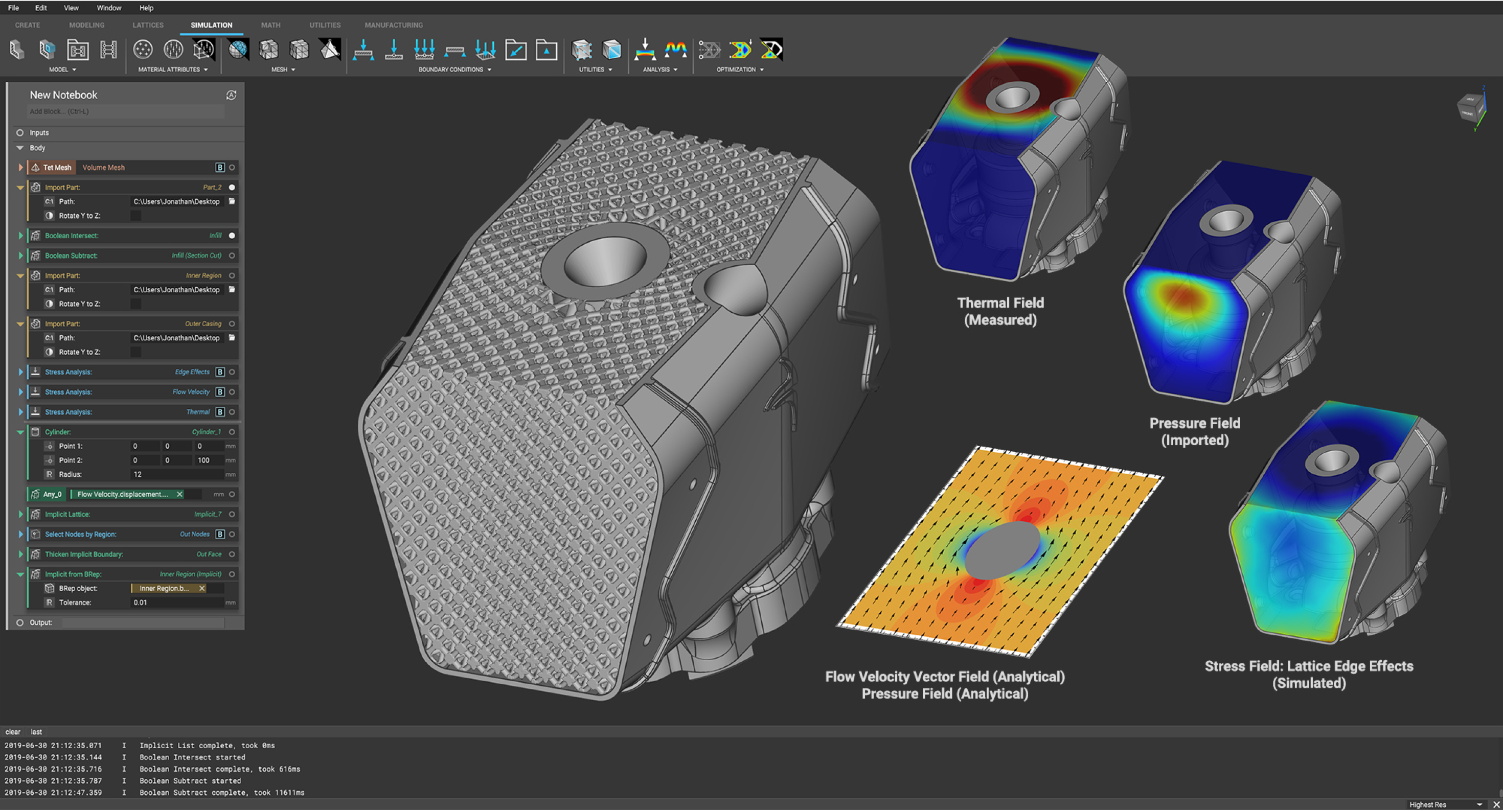
The team expects to employ further the software’s field-driven simulation capabilities that drive how a model is generated based on a range of multiphysical inputs, including temperature, flow velocity and stress, as well as pressure (Fig. 4). Reusable workflows have allowed designers throughout this project to regenerate models without having to start from scratch each time, with the software’s implicit algorithms dramatically slashing computational run times.
“We’ve definitely come to the conclusion that, in the laboratory anyway, our new lattice-cylinder design is a better mousetrap than our fin cylinder—which is a big deal,” says Hilbert. “We now know that we’re in the ballpark in terms of lattice density. From here on out it’s a matter of using nTop Platform to fine-tune all the design parameters we need, and to make the final tweaks for production.” 3DMP
Article provided by nTopology, New York, NY; 917/983-9257, www.ntopology.com, email info@ntopology.com.
See also: Renishaw Inc., Ntopology
Technologies:


 “In my experience with moving back and forth between the computer-aided engineering and the testing realms, honing in on that final design always requires a real-world check,” Hilbert says. “I use those digital-to-physical iterative loops in order to calibrate my models and make great designs.”
 Video
Video